08-InputOutput, 09-SecondaryStorage, 10-FileSystems | CSCI 340
Problem 1 [I/O]: I/O request life cycle
Section titled “Problem 1 [I/O]: I/O request life cycle”Describe in detail the life cycle of an I/O request such as “read”. That is, explain the entire set of steps taken from the time the user app issues the “read” system call until the system call returns with the data from the kernel. Assume that the I/O request completes successfully.
Solution
Elaboration (by LLM)
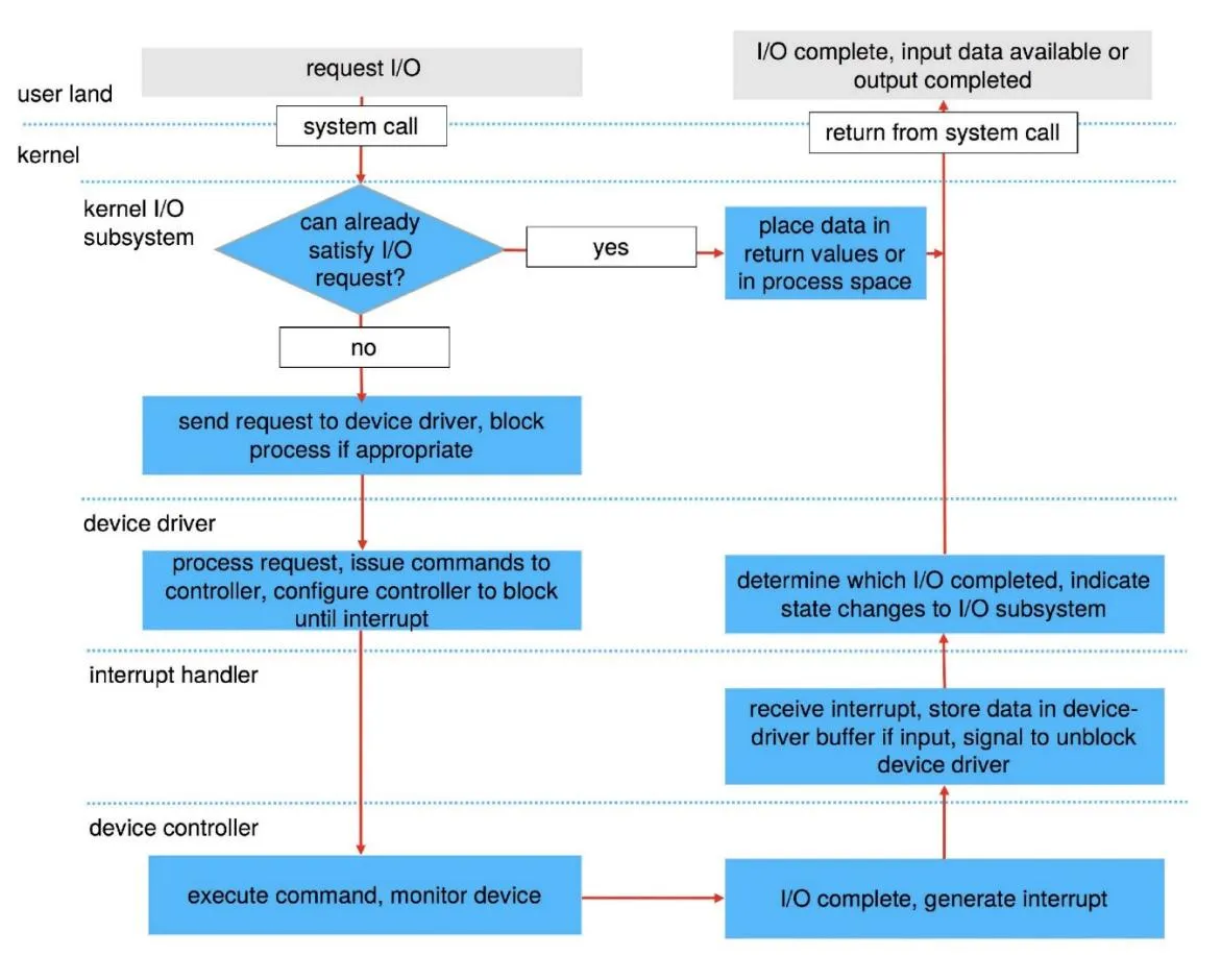
The diagram shows the I/O life cycle across five distinct layers: user land, kernel I/O subsystem, device driver, interrupt handler, and device controller. The flow splits into a fast path (cache hit) and a slow path (physical I/O). Let’s walk through each step.
The Left Side: Issuing the Request (Going Down)
Step 1 — User Land: Request I/O
The user application calls a system call such as read(fd, buf, n). This triggers a trap into the kernel, switching the CPU from user mode to kernel mode. Execution now enters the kernel I/O subsystem.
Step 2 — Kernel I/O Subsystem: Can we already satisfy the request?
The kernel first checks whether it can serve the request immediately — typically by looking in the buffer/page cache, which stores recently accessed disk data in RAM.
- Yes (fast path): The data is already in memory. The kernel places the data in the return values or copies it into the process’s address space, then jumps directly to “return from system call.” No physical I/O is needed.
- No (slow path): The data isn’t cached. The kernel must go to the hardware.
Step 3 — Kernel I/O Subsystem: Send request to device driver, block process if appropriate
For blocking I/O (the default), the kernel suspends (blocks) the calling process and places it in a wait queue. The request is handed off to the appropriate device driver.
Step 4 — Device Driver: Process request, issue commands to controller
The device driver translates the abstract OS request into hardware-specific commands — writing to controller registers, setting up DMA transfers, etc. The controller is configured to block (wait) until the hardware operation finishes and an interrupt fires.
Step 5 — Device Controller: Execute command, monitor device
The hardware physically carries out the operation: for a disk read, this means moving the actuator arm to the right cylinder, waiting for the platter to rotate, and transferring bytes (usually via DMA) into a kernel buffer.
The Right Side: Completion (Going Up)
Step 6 — Device Controller: I/O complete, generate interrupt
Once the hardware finishes, the device controller raises a hardware interrupt signal to the CPU.
Step 7 — Interrupt Handler: Receive interrupt, store data, signal device driver
The CPU pauses its current work and runs the registered interrupt handler. The handler:
- Acknowledges the interrupt so the controller knows it was received.
- For input operations, stores the incoming data in the device driver’s buffer.
- Signals (unblocks) the device driver to continue processing.
Step 8 — Device Driver: Determine which I/O completed, indicate state changes to I/O subsystem
The device driver inspects the result of the operation (success or error) and reports the state change back up to the kernel I/O subsystem, which can now wake the blocked process.
Step 9 — Kernel I/O Subsystem: Place data in return values or process space
The kernel copies the data from the kernel buffer into the user process’s address space (the buffer the user passed to read()).
Step 10 — User Land: Return from system call
The CPU switches back to user mode. The read() system call returns the number of bytes read, and the user application resumes execution with its buffer filled.
Summary of the Two Paths
User App: read(fd, buf, n) │ ▼ [system call / trap into kernel] ┌─────────────────────────┐ │ Kernel I/O Subsystem │ │ Can satisfy request? │ └──────────┬──────────────┘ NO │ YES │ └──────────────────────────────────────────────► ▼ │ Send to device driver Copy data to process space Block process │ │ │ ▼ [device driver layer] │ Issue commands to controller │ │ │ ▼ [device controller layer] │ Execute command (seek, rotate, DMA transfer) │ │ │ └──► I/O complete → Generate Interrupt │ │ │ ▼ [interrupt handler] │ Store data in driver buffer │ Signal driver │ │ │ ▼ [device driver] │ Report completion to I/O subsystem │ │ │ ▼ [kernel I/O subsystem] │ Place data in process space ──────────────────────►┘ │ ▼ Return from system call → User land resumesProblem 2 [I/O]: Device drivers
Section titled “Problem 2 [I/O]: Device drivers”What’s a device driver? Why is it necessary to implement a new device driver for each OS?
Solution
A device driver is a specialized software component that acts as an intermediary between the operating system and a specific hardware peripheral. It translates high-level OS commands (like “write data”) into the low-level electrical signals or commands understood by the hardware. Implementing a new driver for each OS is necessary because:
- Different Kernels: Every OS has a unique kernel architecture, internal API, and data structures. A driver written for the Windows kernel cannot communicate with the Linux or macOS kernel.
- Management Models: Different operating systems handle interrupts, memory management, and I/O scheduling in distinct ways, requiring the driver to be tailored to those specific system behaviors.
Private Concise answer (by LLM)
A device driver is a software component that sits between the OS and a hardware peripheral, translating abstract kernel requests into the device’s specific command language. Each OS needs its own driver because kernels expose different internal APIs, data structures, and interrupt/memory management mechanisms — a driver written for one kernel will not compile or run on another.
Concise answer (by LLM):
A device driver is software that translates generic OS commands into hardware-specific instructions for a particular peripheral; each OS requires its own driver because kernel APIs, interrupt handling, and memory management models differ entirely between operating systems.
Elaboration (by LLM)
Think of a device driver as a translator sitting between two parties that speak completely different languages: the OS and the hardware.
What a Device Driver Does
When you call write(fd, "hello", 5) to send bytes over a serial port, the OS doesn’t know anything about voltage levels, baud rates, or UART registers. The device driver bridges that gap:
High-level OS command Device Driver Hardware Registers───────────────────── ───────────── ───────────────── write(fd, buf, 5) ──► translate to: ──► UART_TX_REG = 'h' port-specific UART_TX_REG = 'e' register writes ... etc.A driver typically implements a set of standard function pointers that the OS calls (e.g., open, read, write, ioctl, release). This is how the VFS can treat every device uniformly from above while the driver handles hardware-specific details below.
Why Each OS Needs Its Own Driver
Imagine you have a graphics card. The card’s hardware interface (its registers, memory layout, DMA protocol) is fixed — it doesn’t change. But the software environment it must plug into is completely different on each OS:
Linux
- Drivers are kernel modules (
.kofiles) - Use Linux kernel APIs:
kmalloc,request_irq,pci_enable_device - Register with subsystems like
struct file_operations - Compiled against the specific kernel version’s headers
Windows
- Drivers use the Windows Driver Model (WDM) or KMDF
- Use Windows APIs:
ExAllocatePool,IoAllocateIrp,WdfDeviceCreate - Interact with the I/O Manager via IRP (I/O Request Packets)
- Must be signed and deployed through INF files
Even though the underlying hardware is the same, the driver code must be completely rewritten because:
- Kernel APIs differ — function names, calling conventions, and data structures are entirely OS-specific.
- Interrupt handling differs — how a driver registers for and acknowledges interrupts is defined by each OS separately.
- Memory management differs — allocating DMA-capable memory uses different mechanisms per OS.
- Security and loading models differ — how drivers are verified, loaded, and sandboxed is OS-specific.
This is why hardware vendors ship separate driver packages for Windows, Linux, and macOS for the exact same physical device.
Problem 3 [I/O]: Linux I/O device classification
Section titled “Problem 3 [I/O]: Linux I/O device classification”Briefly explain how Linux classifies all I/O devices. Give one example of an I/O device under each category.
Solution
Linux classifies I/O devices into three primary categories:
- Block Devices: These store data in fixed-size blocks (e.g., 512 or 4096 bytes) and allow for random access, meaning the OS can jump to any block.
- Example: Hard Disk Drive (HDD) or Solid State Drive (SSD).
- Character Devices: These handle data as a stream of individual bytes or characters. They do not support random access; data is read or written sequentially.
- Example: Keyboard or Serial Port.
- Network Devices: These are accessed through the BSD socket interface rather than the standard file system. They handle data packets rather than streams or blocks.
- Example: Ethernet Card or Wi-Fi Adapter.
Private Concise answer (by LLM)
Linux classifies devices into three types:
- Block devices: random-access, fixed-size-chunk storage (e.g., HDD, SSD)
- Character devices: sequential byte-stream I/O, no random access (e.g., keyboard, serial port)
- Network devices: packet-based, accessed via the socket interface rather than
/dev(e.g., NIC, Wi-Fi adapter)
The classification determines which kernel interface and system calls apply to each device.
Concise answer (by LLM):
Linux classifies I/O devices into three categories:
- Block devices: random-access, fixed-size blocks (e.g., HDD, SSD)
- Character devices: sequential byte streams, no random access (e.g., keyboard, serial port)
- Network devices: packet-based, accessed via the socket interface (e.g., Ethernet card)
Elaboration (by LLM)
Linux’s device classification reflects the fundamental differences in how hardware produces and consumes data. Each category maps to a different access model, which shapes how the OS (and your programs) interact with the device.
Block Devices — Random-Access Storage
Block devices expose storage as an array of fixed-size, independently addressable units called blocks. Because any block can be read or written in isolation, they support true random access.
Block Device (e.g., /dev/sda):
 Block 0   Block 1   Block 2   Block 3   ...   Block N┌────────┬─────────┬─────────┬─────────┬─────┬─────────┐│ 512 B  │  512 B  │  512 B  │  512 B  │ ... │  512 B  │└────────┴─────────┴─────────┴─────────┴─────┴─────────┘     ▲                  ▲  read(block=0)     read(block=2)  ← can jump directly, no need to read block 1
The OS layers a buffer cache on top of block devices so that frequently accessed blocks stay in RAM, reducing physical I/O.
Character Devices — Sequential Byte Streams
Character devices produce or consume data as an unbuffered, sequential stream of bytes. There is no concept of “jump to position N” — data must flow in order.
Character Device (e.g., /dev/ttyS0 — serial port):
You type: H → e → l → l → o                 ↓        [stream, byte by byte, in order]                 ↓          application reads one byte at a time
This model fits input peripherals (keyboards, mice) and communication links (serial ports, USB serial adapters) naturally.
Network Devices — Packet-Based, Socket Interface
Network devices don’t appear in /dev at all. Instead of read()/write(), they are accessed through the BSD socket API (socket(), send(), recv()). The data unit is a packet, not a block or a byte stream.
Network Device (e.g., eth0):
Application    │   socket(AF_INET, SOCK_STREAM, ...)    │   send(sock, data, len, ...)    ▼ TCP/IP Stack  ──►  [Packet]  ──►  NIC Hardware  ──►  Network
Because network data has no file-system representation, it travels through the network stack and is framed into packets with headers — a fundamentally different model from block and character devices.
Practical View in the File System
ls -l /dev/sda # block device: brw-rw---- 1 root disk 8, 0ls -l /dev/tty0 # character device: crw--w---- 1 root tty 4, 0ip link show eth0 # network device: doesn't appear in /dev at allThe b and c prefixes in ls -l output directly indicate block vs. character classification.
Problem 4 [I/O]: I/O device naming
Section titled “Problem 4 [I/O]: I/O device naming”How does Linux “name” I/O devices? Is it different than Windows? If so, how?
Solution
Linux “names” I/O devices by representing them as special files located in the /dev directory. This follows the “everything is a file” philosophy, where the OS interacts with hardware using standard file operations like read() and write(). Here is a comparison of naming conventions between Linux & Windows:
- Linux (Path-based): Devices are identified by hierarchical paths.
- Storage: /dev/sda (first SATA/SCSI drive), /dev/nvme0n1 (NVMe drive).
- Terminals: /dev/tty0.
- Windows (Letter/Interface-based): Devices are identified by drive letters or internal object namespaces (separate namespaces)
- C: or D: for disk drives, COM1, COM2 etc. for serial ports.
Private Concise answer (by LLM)
Linux follows the “everything is a file” philosophy by representing every device as a special file under /dev/, so standard open/read/write calls work on hardware just as on regular files. Windows takes a different approach: storage gets drive letters (C:, D:) and other peripherals get interface-specific names like COM1, each in separate namespaces.
Concise answer (by LLM):
Linux names devices as special files under /dev/ (e.g. /dev/sda, /dev/tty0), following the “everything is a file” philosophy so standard I/O calls work on hardware; Windows instead uses drive letters (C:, D:) and interface-specific names (COM1) in separate namespaces.
Elaboration (by LLM)
The difference in device naming reflects two fundamentally different design philosophies about how an OS should expose hardware to software.
Linux: “Everything is a File”
Linux follows the Unix philosophy that hardware devices should be accessible through the same interface as regular files. Device files live under /dev/ and can be opened, read, and written using standard POSIX I/O calls.
/dev/├── sda ← first SATA/SCSI disk (whole disk)│ ├── sda1 ← first partition│ └── sda2 ← second partition├── nvme0n1 ← first NVMe SSD│ └── nvme0n1p1 ← first partition├── tty0 ← first virtual console (character device)├── ttyS0 ← first serial port├── null ← discards all writes, returns EOF on read└── random ← cryptographic random number generatorBecause device files obey the file interface, standard tools work directly on hardware:
# Read the raw first 512 bytes (boot sector) of a diskdd if=/dev/sda bs=512 count=1 | hexdump -C
# Write directly to a terminalecho "hello" > /dev/tty0
# Generate random byteshead -c 16 /dev/random | hexdumpWindows: Drive Letters and Separate Namespaces
Windows uses a fundamentally different naming model. Storage volumes get assigned drive letters (C:, D:, E:), and other devices use type-specific identifiers (COM1 for serial ports, LPT1 for parallel ports). Internally, Windows uses an Object Manager namespace (\\.\PhysicalDrive0, \\.\COM1) to access raw devices, but this is separate from the drive letter namespace exposed to users.
Linux
- All devices:
/dev/sda,/dev/ttyS0 - Unified file namespace
- Access via
open(),read(),write() - Permissions via standard file permissions (
chmod)
Windows
- Disks:
C:\,D:\ - Serial:
COM1,COM2 - Raw device:
\\.\PhysicalDrive0 - Separate namespaces for different device types
Problem 5 [I/O]: I/O call semantics
Section titled “Problem 5 [I/O]: I/O call semantics”Briefly explain the I/O call semantics available in Linux. If you have a single threaded application but multiple file descriptors to read from, which I/O call semantic makes more sense? Would your answer change if you have a multi-threaded application?
Solution
Linux provides three primary I/O call semantics that define how a process interacts with the kernel during data transfer:
- 1. Blocking (Synchronous) I/O: The default behavior where the calling process is suspended (put into a wait state) until the I/O operation completes. It is simple to program but inefficient for a single thread managing multiple devices, as the thread cannot perform any other tasks while waiting. If we want a single thread to handle multiple descriptors, we must use I/O Multiplexing with select/poll system call.
- 2. Non-Blocking I/O: The I/O call returns immediately, regardless of whether the operation finished. If no data is ready, it returns a specific error code (like EAGAIN). This allows a process to “poll” multiple devices, though it is most effectively used with I/O Multiplexing (select, poll, or epoll) to monitor many file descriptors at once.
- 3. Asynchronous I/O (AIO): The process initiates an I/O request and continues execution immediately while the kernel performs the operation in the background. Once the transfer is complete, the kernel notifies the process via a signal or a callback. This is the most complex to implement but offers high performance for I/O-heavy applications.
For a single-threaded application with multiple file descriptors, I/O Multiplexing makes the most sense. It allows the single thread to efficiently wait on all descriptors simultaneously without wasting CPU cycles on “busy-waiting” (polling) or getting stuck on one inactive descriptor while others have data ready. In a multi-threaded design, you could use Blocking I/O by assigning one thread per file descriptor. However, if you have thousands of descriptors, I/O Multiplexing remains more efficient to avoid the high memory and context-switching overhead of managing too many threads. This is why Node.js uses a single thread and I/O multiplexing to handle thousands of HTTP requests/sec.
Private Concise answer (by LLM)
Linux offers three I/O modes:
- Blocking: the caller sleeps until the operation completes
- Non-blocking: returns
EAGAINimmediately if no data is ready - Asynchronous: the caller continues immediately; the kernel signals completion later via a callback or signal
For a single thread managing many file descriptors, I/O multiplexing (select/poll/epoll) is best — it blocks until any one descriptor is ready, avoiding busy-waiting and thread proliferation. For multi-threaded apps, blocking I/O per thread works at small scale, but multiplexing scales better as descriptor counts grow.
Concise answer (by LLM):
Linux offers three I/O modes:
- Blocking: thread sleeps until the operation completes
- Non-blocking: returns
EAGAINimmediately if no data is ready - Asynchronous: call returns immediately; the kernel notifies on completion via signal or callback
For a single thread with multiple file descriptors, I/O multiplexing (select/poll/epoll) is best; for multi-threaded apps, blocking I/O per thread works at small scale but multiplexing scales better for large descriptor counts.
Elaboration (by LLM)
The three I/O semantics differ in one key dimension: when does the calling thread get control back?
1. Blocking I/O
The thread hands off the request and goes to sleep until the data arrives. Simple to reason about, but the thread is completely unavailable during the wait.
// Thread calls read() on a socket with no data yetssize_t n = read(fd, buf, 1024);// ← Thread is BLOCKED here, doing nothing, until data arrives// Only resumes when read completesprintf("Got %zd bytes\n", n);2. Non-Blocking I/O
The call returns immediately. If no data is ready, it returns -1 with errno == EAGAIN instead of sleeping. The application must repeatedly check (“poll”) until data is available.
fcntl(fd, F_SETFL, O_NONBLOCK); // mark fd as non-blocking
while (1) { ssize_t n = read(fd, buf, 1024); if (n == -1 && errno == EAGAIN) { // No data yet — do other work or try again do_other_work(); continue; } // Data available process(buf, n); break;}Polling in a tight loop wastes CPU. The right pattern is to combine non-blocking I/O with I/O multiplexing.
3. I/O Multiplexing (select / poll / epoll)
A single thread can monitor many file descriptors at once and block only until any one of them becomes ready. This is the classic pattern for servers handling many concurrent connections.
// Watch fd1 and fd2 simultaneouslyfd_set readfds;FD_ZERO(&readfds);FD_SET(fd1, &readfds);FD_SET(fd2, &readfds);
select(max_fd + 1, &readfds, NULL, NULL, NULL);// Blocks until at least one fd has data
if (FD_ISSET(fd1, &readfds)) { /* handle fd1 */ }if (FD_ISSET(fd2, &readfds)) { /* handle fd2 */ }4. Asynchronous I/O (AIO)
The thread submits the I/O request and immediately continues. The kernel signals completion later (via a callback or signal). The thread never waits at all.
struct aiocb cb = { .aio_fildes = fd, .aio_buf = buf, .aio_nbytes = 1024 };aio_read(&cb); // returns immediatelydo_other_work(); // runs while kernel performs I/O in the background// ... later, check status or receive signal:while (aio_error(&cb) == EINPROGRESS) { /* still in progress */ }ssize_t n = aio_return(&cb);Answering the Design Question
Single-threaded, multiple FDs
Use I/O Multiplexing (epoll on Linux for scale). One thread efficiently waits on all descriptors simultaneously. No CPU is wasted. No risk of being stuck waiting on one idle fd while another has data.
This is how Node.js, nginx, and Redis handle thousands of connections with a single thread.
Multi-threaded application
You could use Blocking I/O with one thread per fd — simple to code and perfectly fine at small scale. But for thousands of descriptors, the thread overhead (stack memory ~8MB each, context switching cost) becomes prohibitive. I/O multiplexing in a thread pool is again preferred.
Problem 6 [I/O]: Device Independent Software layer functions
Section titled “Problem 6 [I/O]: Device Independent Software layer functions”List 4 functions of the Device Independent Software layer.
Solution
The Device-Independent Software Layer provides a uniform interface to user-level applications by performing several critical roles:
- Scheduling: It manages and orders I/O requests via per-device queues to optimize hardware throughput (e.g., minimizing disk seek times).
- Buffering: It temporarily stores data in memory during transfers to handle asynchronous arrivals (like network packets) and to bridge the gap between different transfer sizes (e.g., matching a 10 byte write to a 4-KB disk block).
- Caching: It maintains copies of recently accessed data in fast memory (the Disk I/O Cache) to avoid redundant, slow physical hardware access.
- I/O State Management: The kernel tracks the current state of all active I/O, including open file tables, network connections, and character device positions, to ensure data is routed correctly to the requesting process.
Private Concise answer (by LLM)
The Device-Independent Software (DIS) layer provides four functions uniformly across all device types:
- Scheduling: reorders queued I/O requests to maximize hardware throughput
- Buffering: bridges size and timing mismatches between devices and applications
- Caching: keeps recently accessed data in RAM to avoid repeat hardware access
- I/O state management: tracks open files and connection state so completed I/O is delivered to the right process
Concise answer (by LLM):
The Device-Independent Software layer provides four functions:
- Scheduling: orders I/O requests for hardware efficiency
- Buffering: holds data in memory to bridge size/timing mismatches
- Caching: serves repeated reads from RAM without hitting hardware
- I/O state management: tracks open file tables and connection state so data reaches the right process
Elaboration (by LLM)
The Device-Independent Software (DIS) layer sits between the device drivers (which speak hardware) and the user-facing system calls (which speak files and bytes). Its job is to provide a uniform, hardware-agnostic interface while handling concerns that would otherwise be duplicated in every driver.
Think of it like a post office sorting room: it doesn’t care whether the letter came from FedEx or UPS — it handles scheduling, routing, and buffering in one central place.
1. Scheduling
Different I/O requests arrive at different times. The DIS layer queues them and reorders them to maximize hardware efficiency.
Incoming requests (random order): block 500, block 2, block 490, block 50 ↓ [I/O Scheduler — e.g., elevator algorithm] ↓Reordered for efficiency: block 2, block 50, block 490, block 500 ↓ Device Driver (now causes less seeking)For disks, this dramatically reduces seek time. For SSDs, scheduling is simpler since there’s no mechanical arm.
2. Buffering
Data often arrives or is produced at a different rate or granularity than it is consumed. The DIS layer bridges this mismatch using in-memory buffers.
- A network packet arrives as 1500 bytes, but the application only
read()s 100 bytes at a time — the buffer holds the rest. - An application writes 10 bytes, but a disk block is 4096 bytes — the buffer accumulates writes until a full block can be flushed.
App writes: 10B → 10B → 10B → ... (many small writes) ↓ bufferingDisk sees: ← one 4096-byte block write → (efficient)3. Caching
The DIS layer keeps a copy of recently used disk blocks in RAM (the page cache). On a subsequent read of the same data, the kernel can serve it from memory without involving the hardware at all.
First read(block 42): cache MISS → goes to disk → fills cache → returns dataSecond read(block 42): cache HIT → returns data from RAM immediatelyThis is why re-reading the same file is dramatically faster than reading it for the first time.
4. I/O State Management
The kernel must track which process owns which open file descriptor, what position each is at, and what state each connection is in. The DIS layer maintains:
- The open file table (tracks all currently open file descriptors across all processes)
- Character device positions (the current read/write cursor for sequential devices)
- Network connection state (e.g., TCP state machine: LISTEN, ESTABLISHED, CLOSE_WAIT, etc.)
This ensures that when an I/O operation completes, the data is routed to exactly the right process and file descriptor.
Problem 7 [I/O]: High-level I/O libraries
Section titled “Problem 7 [I/O]: High-level I/O libraries”Given that the OS already provides “read” and “write” system calls to read from/write to an I/O device, why do most programmers still prefer using a high-level I/O library to perform I/O? Briefly explain.
Solution
Most programmers prefer high-level I/O libraries (like stdio.h in C or java.io) over raw system calls for three primary reasons:
- Efficiency via User-Space Buffering: System calls are expensive because they require a context switch from user mode to kernel mode. High-level libraries buffer data in user space, grouping many small “writes” into a single system call to minimize this overhead.
- Portability: System call interfaces (like read or write) vary between operating systems (e.g., POSIX vs. Windows API). High-level libraries provide a consistent, platform-independent interface, allowing the same code to run on different OSs.
- Convenience and Formatting: Libraries provide sophisticated formatting tools (like printf or scanf) that handle complex data type conversions (integers, floats, strings) which raw byte-oriented system calls do not support.
Private Concise answer (by LLM)
High-level I/O libraries like stdio.h are preferred over raw system calls for three reasons:
- User-space buffering: batches many small writes into fewer, cheaper system calls
- Portability: hides OS-specific differences so the same code (
fopen/fread) compiles unchanged on Linux and Windows - Formatting: provides
printf/scanf-style type conversion that rawwrite/readcannot
Concise answer (by LLM):
High-level I/O libraries are preferred over raw system calls for three reasons:
- User-space buffering: batches many small writes into one system call, reducing expensive context switches
- Portability: abstracts OS-specific call differences behind a consistent interface
- Formatting: provides
printf/scanf-style data conversion that raw byte calls don’t support
Elaboration (by LLM)
Raw system calls like read() and write() are powerful but intentionally minimal — they just move raw bytes. High-level libraries like stdio.h (C) or java.io (Java) are built on top of these system calls to make I/O practical for real-world programming.
1. Efficiency via User-Space Buffering
Every system call has a fixed cost: the CPU must switch from user mode to kernel mode (saving registers, changing protection levels, etc.), even if you’re only writing 1 byte. Doing this thousands of times is expensive.
// Naive approach: one system call per character (very slow)for (int i = 0; i < 10000; i++) { write(fd, &data[i], 1); // 10,000 system calls!}
// Library approach: fputc buffers in user spacefor (int i = 0; i < 10000; i++) { fputc(data[i], fp); // accumulates in a 4KB buffer}fflush(fp); // ONE system call flushes everythingThe library accumulates data in a user-space buffer (typically 4–8 KB) and only calls write() when the buffer is full or explicitly flushed. This can reduce system call overhead by orders of magnitude.
2. Portability
Raw system calls are OS-specific:
Linux/POSIX
int fd = open("file.txt", O_RDONLY);read(fd, buf, n);close(fd);Windows API
HANDLE h = CreateFile("file.txt", GENERIC_READ, 0, NULL, OPEN_EXISTING, 0, NULL);ReadFile(h, buf, n, &bytesRead, NULL);CloseHandle(h);The stdio.h versions (fopen, fread, fclose) compile and run correctly on both without any changes. The library handles the OS-specific translation internally.
3. Convenience and Formatting
Raw write() only accepts a pointer and a byte count. It has no concept of integers, floats, or formatted strings. Libraries provide rich formatting:
// With raw write(): you must manually convert types to byteschar buf[64];int len = snprintf(buf, sizeof(buf), "Score: %d, Avg: %.2f\n", score, avg);write(fd, buf, len);
// With stdio: direct and readablefprintf(fp, "Score: %d, Avg: %.2f\n", score, avg);Similarly, scanf and fscanf handle parsing formatted input — detecting integers, floats, and strings from a raw byte stream — which read() alone cannot do.
Problem 8 [Secondary Storage]: Disk cylinders
Section titled “Problem 8 [Secondary Storage]: Disk cylinders”What’s is a cylinder (as it applies to disks). Briefly explain.
Solution
A cylinder is the set of all tracks that are at the same radial distance from the center of the spindle across all platter surfaces.
Concise answer (by LLM):
A cylinder is the collection of all tracks at the same radial distance from the spindle center, spanning every platter surface; because all read/write heads share one arm, data within the same cylinder can be read without any seek movement.
Elaboration (by LLM)
To understand a cylinder, you first need to understand the physical structure of a hard disk drive.
HDD Physical Structure
A hard disk contains multiple platters (circular magnetic disks) stacked on a shared spindle, all spinning together. Each platter surface has a read/write head mounted on a common actuator arm. All heads move together — when the arm moves, every head moves to the same radial position simultaneously.
Each platter surface is divided into concentric rings called tracks. Track 0 is at the outer edge, track N is near the center.
What Makes a Cylinder
Since all heads are always at the same radial position at the same time, the set of tracks at a given radial distance — one track per platter surface — forms a vertical “cylinder” shape through the stack:
Actuator arm (all heads move together) │ ┌─────────┼─────────┐ │ ───────●─────── │ ← Platter surface 0, Track 3 ┐ │ │ │ │ ───────●─────── │ ← Platter surface 1, Track 3 ├─ Cylinder 3 │ │ │ │ ───────●─────── │ ← Platter surface 2, Track 3 ┘ └───────────────────┘ (side view)All the tracks marked “Track 3” across all platters — at the same radial distance — together form Cylinder 3.
Why Cylinders Matter
Because all heads share the same arm, reading data from different tracks within the same cylinder requires no seek time — the arm doesn’t move. The OS and file system try to store related data within the same cylinder to minimize mechanical seek operations, which are the slowest part of disk access.
Problem 9 [Secondary Storage]: Rotational latency
Section titled “Problem 9 [Secondary Storage]: Rotational latency”What’s rotational latency (as it applies to disks). Briefly explain.
Solution
Rotational latency (or rotational delay) is the time required for the specific disk sector requested by the OS to rotate under the read/write head after the head has reached the correct track.
Concise answer (by LLM):
Rotational latency is the wait after a seek for the target sector to spin around to the read/write head position; on average it equals half a full disk revolution.
Elaboration (by LLM)
Once the actuator arm has completed its seek and placed the read/write head over the correct track (cylinder), the disk’s work isn’t done yet. The head is now in the right lane of a spinning highway — but it must wait for the exact target sector to come around to its position.
Visualizing Rotational Latency
        Head position (fixed after seek)              │              ▼    ┌─────────●─────────┐    │    ┌─────────┐    │    │    │  Disk   │ ←  rotating clockwise    │    │ ┌─────┐ │    │    │    │ │     │ │    │    │    │ └──★──┘ │    │   ★ = target sector (currently on far side)    │    │         │    │    │    └─────────┘    │    └───────────────────┘
    Must wait for ★ to rotate around to the head (●)
The disk is always spinning (at 5400, 7200, or 15000 RPM). The head can’t “jump” to the sector — it must wait for the platters to bring the sector to it.
Best and Worst Cases
- Best case (0ms): The target sector happens to be just arriving under the head at the exact moment the seek ends. No wait at all.
- Worst case (full rotation): The target sector just passed the head a moment before the seek completed. The head must wait for nearly one full revolution.
- Average case (half rotation): On average, the target sector is half a rotation away — this is the average rotational latency.
Relationship to Seek Time
Total disk access time has three components:
Rotational latency is often comparable in magnitude to seek time and is the second major source of mechanical delay in HDDs. SSDs eliminate it entirely by having no spinning platters.
Problem 10 [Secondary Storage]: Average rotational latency
Section titled “Problem 10 [Secondary Storage]: Average rotational latency”What’s the average rotational latency for a disk that rotates at 7200rpm?
Solution
For a disk rotating at 7200 RPM, the average rotational latency is:
- Rotations per second: (7200 rotations)/(60 seconds) = 120 rotations/sec
- Time for one full rotation: 1sec/120 = 1000ms/120 = 8.33ms
- Average Rotational Latency: 8.33ms/2 = 4.17ms
Concise answer (by LLM):
At 7200 RPM, one full rotation takes , so the average rotational latency (half a rotation) is 4.17 ms.
Elaboration (by LLM)
The calculation follows directly from the definition of average rotational latency: since the target sector is equally likely to be anywhere around the disk, it is on average half a revolution away.
Step-by-step:
Step 1 — Convert RPM to rotations per second:
Step 2 — Find the time for one full rotation:
Step 3 — Average latency is half a rotation:
Intuition: Why half a rotation?
The target sector is equally likely to be at any angular position relative to the head. The expected wait is the average of all possible angular distances from 0° to 360°, which is 180° — exactly half a turn.
Comparison across common disk speeds:
| RPM | Full rotation | Avg rotational latency |
|---|---|---|
| 5400 | 11.11 ms | 5.56 ms |
| 7200 | 8.33 ms | 4.17 ms |
| 10000 | 6.00 ms | 3.00 ms |
| 15000 | 4.00 ms | 2.00 ms |
Faster disks reduce rotational latency, but even at 15,000 RPM it’s still measured in milliseconds — millions of times slower than RAM access (~nanoseconds). This is why SSDs, which have zero rotational latency, offer such a dramatic performance advantage.
Problem 11 [Secondary Storage]: Seek time
Section titled “Problem 11 [Secondary Storage]: Seek time”What’s seek time (as it applies to disk)? Briefly explain.
Solution
Seek time is the time required for the disk’s read/write head to physically move the actuator arm to the specific cylinder (track) where the requested data is located.
Concise answer (by LLM):
Seek time is the mechanical delay for the actuator arm to swing the read/write head to the correct track; it is typically the largest component of total HDD access time and the primary reason disk scheduling algorithms exist.
Elaboration (by LLM)
Seek time is the first and often largest component of disk access latency. It is purely mechanical: the actuator arm must swing to the correct radial position before any data can be read or written.
The Actuator Arm
All read/write heads are attached to a single actuator arm that pivots from one side of the disk stack. Moving the arm is driven by a voice-coil motor (similar to a speaker), which is fast but not instantaneous.
Disk (top view):
          Outer tracks (lower cylinder numbers)   ┌──────────────────────────────────┐   │        ╔══════════════╗          │   │        ║   Platters   ║          │   │        ║              ║◄── Head  ●──────── Actuator arm ──[pivot]   │        ║              ║          │   │        ╚══════════════╝          │   └──────────────────────────────────┘          Inner tracks (higher cylinder numbers)
  Seek: arm swings so head moves from current cylinder → target cylinder
Components of Seek Time
Seek time itself has sub-phases:
- Acceleration: The arm begins to accelerate toward the target cylinder.
- Coasting: For long seeks, the arm may coast at maximum speed.
- Deceleration: The arm slows as it approaches the target.
- Settling: The head must stabilize precisely over the track before reading (takes a fraction of a millisecond).
Typical Values
- Average seek time (random access across the whole disk): 5–15 ms for HDDs.
- Track-to-track seek time (moving just one cylinder): ~0.5–2 ms.
- Full-stroke seek (outer to inner edge): up to 20+ ms.
Why Disk Scheduling Algorithms Exist
Because seek time dominates access time for random workloads, the OS reorders queued I/O requests to minimize total arm movement. Algorithms like SSTF, SCAN, and C-SCAN are all trying to reduce total seek time across a batch of requests — this is why they matter.
Problem 12 [Secondary Storage]: SSDs vs HDDs
Section titled “Problem 12 [Secondary Storage]: SSDs vs HDDs”Briefly explain the pros and cons of using Non-Volatile Memory (SSDs) compared to hard disks (HDDs).
Solution
Non-Volatile Memory (SSDs)
- Pros:
- Speed: Near-zero seek time and rotational latency because there are no moving parts.
- Durability: Highly resistant to physical shock and vibration.
- Quiet/Efficient: Silent operation and lower power consumption.
- Cons:
- Cost: Higher price per gigabyte compared to HDDs.
- Write Endurance: NAND flash memory cells degrade after a finite number of write cycles (though wear-leveling algorithms mitigate this).
Hard Disk Drives (HDDs)
- Pros:
- Capacity/Cost: Much cheaper for storing massive amounts of data (terabytes).
- Cons:
- Performance: Limited by mechanical speed (seek time and rotational latency).
- Fragility: Moving parts are susceptible to mechanical failure and damage if dropped.
Concise answer (by LLM):
SSDs (no moving parts) are faster, more durable, and quieter than HDDs, but cost more per GB and have a finite NAND write endurance; HDDs remain the better choice for large-capacity bulk storage on a budget.
Elaboration (by LLM)
The core difference between SSDs and HDDs comes down to one thing: SSDs have no moving parts. This single fact cascades into most of the performance, durability, and endurance differences between the two.
Performance: Where SSDs Win Decisively
Recall that HDD access time has three components:
SSDs eliminate the first two entirely:
In practice:
| Metric | HDD (7200 RPM) | SSD (NVMe) |
|---|---|---|
| Sequential read | ~150 MB/s | ~3,500 MB/s |
| Random read (IOPS) | ~100–200 | ~500,000+ |
| Average seek | ~8 ms | ~0.1 ms |
| Rotational latency | ~4 ms | None |
For random access workloads (databases, OS boot), SSDs are dramatically faster. For sequential reads of large files, the gap is smaller.
Write Endurance: Where HDDs Have an Advantage
NAND flash cells physically degrade each time they are erased and rewritten. Each cell has a finite Program/Erase (P/E) cycle limit:
- TLC NAND (common in consumer SSDs): ~300–1,000 P/E cycles
- MLC NAND: ~3,000–10,000 P/E cycles
- SLC NAND: ~100,000 P/E cycles
An HDD platter, by contrast, can be overwritten an essentially unlimited number of times (mechanical wear is the limit, not per-sector endurance).
Wear leveling and the TRIM command help extend SSD life, but for extremely write-heavy workloads, HDD endurance is a genuine advantage.
Cost vs. Capacity
HDDs remain the dominant choice for bulk storage (backups, video archives, NAS systems) because of their price-per-gigabyte advantage. A typical 4TB HDD costs far less than a 4TB SSD, making HDDs the practical choice when capacity matters more than speed.
Problem 13 [Secondary Storage]: SSD physical structure
Section titled “Problem 13 [Secondary Storage]: SSD physical structure”Briefly describe the physical structure of an SSD. That is, what is a page, what is a block as they apply to SSDs. How does an SSD perform the “modify” operation?
Solution
An SSD is composed of NAND flash memory chips, which are organized into a specific hierarchy:
- Page: The smallest unit for reading and writing (typically 4 KB - 16 KB).
- Block: A collection of pages (typically 64 - 256 pages). This is the smallest unit that can be erased. Unlike an HDD, an SSD cannot overwrite data directly because a page must be in an “erased” state before it can be written to. To “modify” data:
-
- Read: The SSD reads the entire block containing the target page into a memory buffer.
-
- Modify: It updates the specific page in the buffer.
-
- Write: It writes the updated data to a new, empty block.
-
- Erase: The old block is marked as “stale” and eventually cleared by Garbage Collection.
-
Concise answer (by LLM):
An SSD organizes NAND flash into pages (smallest read/write unit) grouped into blocks (smallest erasable unit); because pages cannot be overwritten in place, a “modify” requires reading the whole block, updating the target page in a buffer, writing it to a new empty block, then marking the old block stale for garbage collection.
Elaboration (by LLM)
SSD Hierarchy
NAND flash is organized in a strict hierarchy from large to small:
SSD└── Die └── Plane └── Block (smallest erasable unit, e.g., 256 pages × 16 KB = 4 MB) ├── Page 0 (smallest read/write unit, e.g., 16 KB) ├── Page 1 ├── Page 2 │ ... └── Page 255The crucial asymmetry to internalize: pages are written individually, but erased only in whole blocks.
Why Can’t You Overwrite a Page Directly?
NAND flash cells store data as electrical charge. Writing sets specific bits; erasing resets the entire block to all-1s. You cannot selectively reset individual bits within a page — the physics of the memory cell require an erase at block granularity before a cell can be reprogrammed.
Page state machine:
  [Erased: all 1s]  ──write──►  [Written: 0s and 1s]         ▲                               │         └──────── erase (whole block) ◄─┘                   (cannot skip this step to re-write)
The Modify (Read-Modify-Write) Operation
Suppose you want to update 1 KB of data sitting in Page 5 of Block 10:
Block 10 (before modify):  Page 0: [valid data A]  Page 1: [valid data B]  ...  Page 5: [OLD data — target of modify]   ← cannot overwrite in place  ...  Page 255: [valid data Z]
Step 1 — Read: copy entire block into RAM bufferStep 2 — Modify: update Page 5's content in the bufferStep 3 — Write: write all pages to a new, pre-erased Block 77
Block 77 (after write):  Page 0: [valid data A]   ← copied unchanged  Page 1: [valid data B]   ← copied unchanged  ...  Page 5: [NEW data]       ← updated version  ...  Page 255: [valid data Z]  ← copied unchanged
Step 4 — FTL update: logical address now maps to Block 77Step 5 — Mark Block 10 as stale (to be erased later by Garbage Collection)
This is called Write Amplification — updating a small amount of data forces writing a much larger amount. The Write Amplification Factor (WAF) measures this ratio and directly impacts SSD lifespan and performance.
Problem 14 [Secondary Storage]: Flash Translation Layer
Section titled “Problem 14 [Secondary Storage]: Flash Translation Layer”What’s the purpose of the Flash Translation Layer (FTL) in SSDs? How does the SSD update the FTL during garbage collection?
Solution
The Flash Translation Layer (FTL) is a hardware/software component within the SSD controller that maps Logical Block Addresses (LBAs) from the OS to Physical Block Addresses (PBAs) on the NAND flash. Here are some of the purposes of FTL:
- Abstraction: It makes the SSD appear like a traditional hard drive to the OS, hiding the complex flash geometry.
- Wear Leveling: It distributes writes across all physical blocks to ensure the flash cells wear out evenly.
- Bad Block Management: It identifies and skips retired (failed) memory cells.
When the SSD performs Garbage Collection, it moves “valid” pages from a fragmented block to a new, clean block so the old one can be erased.
- Relocation: The controller copies the valid data to a new physical location.
- Table Update: The FTL immediately updates its internal mapping table to point the original logical address to this new physical address.
- Invalidation: The old physical entries are marked as invalid/stale, allowing the block to be safely erased and reused.
Concise answer (by LLM):
The FTL maps logical block addresses (what the OS sees) to physical NAND locations, hiding flash constraints and enabling wear leveling and bad block management; during garbage collection it relocates valid pages to a clean block and updates its mapping table so logical addresses point to the new physical location.
Elaboration (by LLM)
The Core Problem the FTL Solves
The OS thinks of storage as a simple array of fixed-size logical blocks, numbered 0 through N. It reads and writes by logical block address (LBA), e.g., “write data to LBA 1000.”
But NAND flash has a constraint: you can never write to the same physical location twice without erasing it first. If the FTL didn’t exist, the OS would try to update LBA 1000 in-place — which is physically impossible on flash.
The FTL solves this with indirection: LBAs don’t map permanently to physical locations. The mapping can change at any time.
OS: "Write to LBA 1000" │ ▼ FTL Mapping Table ┌────────────────────────┐ │ LBA 1000 → PBA 5023 │ ← first write │ LBA 1000 → PBA 8801 │ ← after an update, remapped └────────────────────────┘ │ ▼ Physical NAND flash PBA 8801: [new data] PBA 5023: [stale — awaiting garbage collection]Garbage Collection and FTL Updates
Over time, physical blocks accumulate a mix of valid pages (still pointed to by the FTL) and stale pages (overwritten, no longer referenced). Before a block can be erased and reused, its valid pages must be relocated:
Fragmented Block (before GC):  Page 0: VALID   ← FTL still points here  Page 1: STALE   ← was overwritten, no longer referenced  Page 2: VALID   ← FTL still points here  Page 3: STALE
GC Step 1 — Relocate valid pages to a clean block:  New Block, Page 0: [copy of old Page 0]  New Block, Page 1: [copy of old Page 2]
GC Step 2 — Update FTL mapping table:  LBA X → now points to New Block, Page 0  LBA Y → now points to New Block, Page 1
GC Step 3 — Erase old block (now entirely stale):  Old Block: [all cells reset to 1s, ready for reuse]
Wear Leveling via the FTL
Because the FTL controls where every write lands physically, it can ensure that writes are spread evenly across all blocks — preventing any single block from being worn out while others remain fresh. Without the FTL’s remapping ability, wear leveling would be impossible.
Problem 15 [Secondary Storage]: TRIM command
Section titled “Problem 15 [Secondary Storage]: TRIM command”Briefly describe the role of the TRIM command sent from the OS to an SSD.
Solution
The TRIM command allows the operating system to inform the SSD controller which blocks of data are no longer considered “in use” (e.g., after a user deletes a file). Here are the roles of TRIM:
- Logical vs. Physical Sync: Without TRIM, an SSD doesn’t know a file was deleted until the OS tries to overwrite those same sectors. TRIM provides this “heads-up” immediately.
- Efficiency: It allows the SSD to skip moving “deleted” data during Garbage Collection, which reduces internal data copying.
- Performance & Lifespan: By reducing unnecessary writes (Write Amplification), TRIM maintains higher write speeds over time and extends the physical life of the NAND flash cells.
Concise answer (by LLM):
TRIM lets the OS notify the SSD which logical blocks are now free (after file deletion), so the SSD can skip copying that dead data during garbage collection, reducing write amplification and preserving both sustained write performance and flash cell lifespan.
Elaboration (by LLM)
The Problem TRIM Solves
When you delete a file on a traditional HDD, the OS simply marks those sectors as “free” in the file system’s metadata. The actual data on the disk isn’t zeroed out — the OS just updates its own records. This is fine for HDDs because they can overwrite any sector directly when needed.
For SSDs, this creates a problem. The SSD controller has no visibility into the file system. From its perspective, every written page is “valid” until told otherwise. So when GC runs, it faithfully copies stale-from-the-OS’s-perspective data to new blocks — wasting write cycles on data that the user already deleted.
Without TRIM:
OS deletes file.txt (occupying LBAs 500–510)  │  ├─ OS marks LBAs 500–510 as "free" in its own metadata  └─ SSD controller: has NO IDEA — still treats those pages as valid
Garbage Collection runs:  └─ SSD copies "deleted" pages to new block (unnecessary work!)     → wastes P/E cycles, slows down GC, increases write amplification
How TRIM Fixes This
When the OS deletes a file, it sends a TRIM command to the SSD identifying the now-unused LBAs:
With TRIM:
OS deletes file.txt (LBAs 500–510)  │  ├─ OS marks LBAs 500–510 as free in its metadata  └─ OS sends: TRIM(LBAs 500–510) to SSD controller
SSD controller:  └─ Marks physical pages mapped to LBAs 500–510 as INVALID
Garbage Collection runs:  └─ Skips invalid pages — does NOT copy them     → only valid, live data is relocated     → less work, less write amplification, faster GC
Impact on Performance and Lifespan
Without TRIM, write performance on SSDs degrades over time as the drive fills up with stale-but-unknown-to-the-SSD data. With TRIM enabled, the SSD can maintain a pool of pre-cleaned blocks, keeping write performance consistent and reducing unnecessary wear on flash cells.
Problem 16 [Secondary Storage]: Write leveling
Section titled “Problem 16 [Secondary Storage]: Write leveling”What’s “write leveling” as it applies to SSDs and why is it needed?
Solution
Wear leveling is a technique used by the SSD controller to distribute write and erase cycles evenly across all physical memory blocks in the drive. Here is why it is needed:
- Finite Lifespan: Each NAND flash memory cell can only be erased and rewritten a limited number of times (its “program/erase” or P/E cycle limit) before it wears out and can no longer reliably store data.
- Preventing Premature Failure: Without wear leveling, the OS might repeatedly write to the same logical sectors (like file system metadata). This would cause those specific physical blocks to fail quickly, rendering the entire drive unusable even if most of the other flash cells are still perfectly healthy.
Concise answer (by LLM):
Wear leveling distributes write/erase cycles evenly across all NAND flash blocks so that frequently written logical sectors don’t burn out specific physical blocks prematurely; it is needed because each flash cell has a finite program/erase cycle limit.
Elaboration (by LLM)
The Root Problem: Uneven Writes
Some logical sectors are written far more frequently than others. File system metadata (directory entries, inode tables, journal logs) can be updated hundreds of times per day, while infrequently changed data (photos, archived documents) might be written once and never touched again.
Without wear leveling, the FTL would always map hot logical sectors to the same physical blocks — burning them out while cold blocks remain nearly pristine.
Without wear leveling (after heavy use):
Block 0:  [WORN OUT — 1000 P/E cycles, unreliable]  ← hot data always mapped hereBlock 1:  [WORN OUT — 1000 P/E cycles, unreliable]Block 2:  [HEALTHY —    10 P/E cycles]               ← cold data, rarely writtenBlock 3:  [HEALTHY —    12 P/E cycles]...Block N:  [HEALTHY —     5 P/E cycles]
Drive fails prematurely despite most cells being healthy!
How Wear Leveling Works
The FTL periodically rotates which physical blocks hold hot data, ensuring all blocks accumulate erase cycles at similar rates:
With wear leveling (dynamic):
Time T1: Hot LBA 0 → Physical Block 0 (write here)Time T2: Hot LBA 0 → Physical Block 1 (rotated to spread wear)Time T3: Hot LBA 0 → Physical Block 2...
Result: All blocks accumulate wear evenly
For static wear leveling, the FTL goes further: it also moves cold data that has been sitting untouched in the same physical blocks for a long time, freeing those blocks to accept new writes and replacing them with other cold data.
Two Types of Wear Leveling
- Dynamic wear leveling: When writing new or updated data, the FTL chooses the least-worn block available. Cold data that never changes stays put.
- Static wear leveling: The FTL proactively relocates cold data from low-wear blocks so those blocks can be used for new writes, achieving more even distribution across the entire drive.
Calculating the Impact
Given a drive with 500 GB capacity, 1000 P/E cycles per block, and a WAF of 2:
With perfect wear leveling, all those cycles are shared across all blocks. Without it, a subset of blocks fails early, reducing effective capacity and drive life significantly.
Problem 17 [File System]: Why file systems are necessary
Section titled “Problem 17 [File System]: Why file systems are necessary”Given that the device independent layer allows a disk to be read in blocks, why is it still necessary to implement a file system?
Solution
Device Independent Layer exports a disk as an array of raw blocks. This is a very low level interface for a disk. Typically, general users would like to see a disk as a set of files and directories. To turn a raw disk into files, directories and permissions, a file system is required. Additionally, a file system is required to track which blocks are free and which are occupied, preventing new files from overwriting existing data.
Concise answer (by LLM):
The device-independent layer only exposes raw numbered blocks; a file system is needed to add naming (files and directories), free-space tracking (so new files don’t overwrite existing ones), and access permissions on top of that raw interface.
Elaboration (by LLM)
Without a file system, you’d have a disk that looks like this:
Raw disk (what the Device-Independent Layer provides):
Block 0:  [0x4D 0x5A 0x90 0x00 0x03 0x00 ...]Block 1:  [0x00 0x00 0x00 0x00 0x00 0x00 ...]Block 2:  [0x48 0x65 0x6C 0x6C 0x6F 0x20 ...]...Block N:  [0x3F 0x2F 0x00 0xFF 0x12 0x44 ...]
Just raw binary data with no structure, no names, no organization. The file system is what transforms this into something usable.
What a File System Adds on Top of Raw Blocks
1. Naming and Hierarchy
A file system provides the directory tree that maps human-readable names to sets of disk blocks:
/├── home/│ └── alice/│ ├── notes.txt → blocks [42, 43, 44]│ └── photo.jpg → blocks [100, 101, ..., 250]└── etc/ └── passwd → blocks [7]Without this, users would have to remember that their essay is stored in blocks 42–44. That’s obviously impractical.
2. Free Space Tracking
The file system maintains a record of which blocks are in use and which are free (typically via a bitmap or free list). Without this:
- Writing a new file could overwrite existing data — the OS would have no way to know block 100 is already used.
- Deleting a file would leave orphaned blocks with no way to reclaim them.
Free block bitmap example:Block: 0 1 2 3 4 5 6 7 8 9 ...Used: 1 1 0 1 0 0 1 1 0 0 ... ▲ ▲ ▲ ▲ ▲ free! free free free free ← available for new files3. Metadata and Permissions
Every file needs associated metadata: owner, permissions, timestamps, and size. The file system stores this in structures like inodes (in Unix). Without them, there’s no way to enforce chmod, no record of when a file was last modified, and no concept of file ownership.
4. Data Integrity
File systems implement journaling (or other consistency mechanisms) to ensure that a crash mid-write doesn’t leave the disk in a corrupt, unrecoverable state — something raw block access has no mechanism for.
Problem 18 [Secondary Storage]: SSTF disk scheduling
Section titled “Problem 18 [Secondary Storage]: SSTF disk scheduling”Assume that the disk head is currently over cylinder 20 and you have disk requests for the following cylinders: 35, 22, 15, 55, 72, 8. In what order would you serve these requests if you were to employ Shortest Seek Time First (SSTF) scheduling algorithm?
Solution
To serve these requests using the Shortest Seek Time First (SSTF) algorithm, we always choose the cylinder closest to the current head position:
- 20 → 22: Closest available.
- 22 → 15: 15 (7 away) is closer than 35 (13 away).
- 15 → 8: 8 (7 away) is closer than 35 (20 away).
- 8 → 35: Only 35, 55, and 72 remain; 35 is the nearest.
- 35 → 55: 55 is closer than 72.
- 55 → 72: Final request.
Final Order: 22, 15, 8, 35, 55, 72.
Elaboration (by LLM)
SSTF is a greedy algorithm — at every step, it picks the globally cheapest next move without looking ahead. Think of it as the disk head being “attracted” to the nearest pending request.
Step-by-step trace:
At each step, we list the remaining requests and calculate their distance from the current head position, then pick the minimum.
| Step | Head at | Remaining requests | Distances | Chosen (min) |
|---|---|---|---|---|
| 1 | 20 | 35, 22, 15, 55, 72, 8 | 15, 2, 5, 35, 52, 12 | 22 |
| 2 | 22 | 35, 15, 55, 72, 8 | 13, 7, 33, 50, 14 | 15 |
| 3 | 15 | 35, 55, 72, 8 | 20, 40, 57, 7 | 8 |
| 4 | 8 | 35, 55, 72 | 27, 47, 64 | 35 |
| 5 | 35 | 55, 72 | 20, 37 | 55 |
| 6 | 55 | 72 | 17 | 72 |
Visual timeline of head movement:
Cylinder: 8 15 20 22 35 55 72 │ │ │ │ │ │ │ ◄────┼───┼───┼─ │ │ │ ③ ② start ① ④ ⑤ ⑥ ◄────── (reverses after ①=22)SSTF’s Weakness: Starvation
SSTF can starve requests at far-away cylinders. If new requests keep arriving near the current head position, a request at cylinder 72 might never get served — the algorithm keeps choosing closer options indefinitely. SCAN-based algorithms were designed to fix this.
Problem 19 [Secondary Storage]: C-SCAN disk scheduling
Section titled “Problem 19 [Secondary Storage]: C-SCAN disk scheduling”Suppose that a disk drive has 5000 cylinders, numbered 0 to 4999. The drive is currently serving a request at cylinder 143, and the previous request was at cylinder 125. The queue of pending requests, in FIFO order, is 86, 1470, 913, 1774, 948, 1509, 1022, 1750, 130. In what order would you serve these requests if you were to employ C-SCAN scheduling algorithm?
Solution
In C-SCAN (Circular SCAN), the disk head moves in one direction (usually towards higher cylinder numbers) and, upon reaching the end, immediately returns to the start without serving requests on the way back. Since the previous request was at 125 and the current is at 143, the head is moving in the increasing direction. Therefore, C-SCAN Service order will be:
- 913
- 948
- 1022
- 1470
- 1509
- 1750
- 1774
- (Head moves to the very end at 4999)
- (Head “wraps around” to the start at 0)
- 86
- 130
Final Sequence: 913, 948, 1022, 1470, 1509, 1750, 1774, 86, 130.
Elaboration (by LLM)
Why C-SCAN instead of SCAN?
Regular SCAN (elevator algorithm) moves in one direction, then reverses and serves requests on the way back. This creates unequal waiting times: cylinders near the turnaround point get served twice as often as cylinders at the far ends. C-SCAN fixes this by treating the disk as a circular structure — it always sweeps in one direction and immediately jumps back to the beginning, providing more uniform waiting times.
Determining Direction
The direction is inferred from the last two positions:
- Previous: 125, Current: 143 → head is moving toward higher cylinders (increasing direction).
Partitioning the Requests
Sort all pending requests: 86, 130, 913, 948, 1022, 1470, 1509, 1750, 1774
Split at the current position (143):
- Above 143 (served first, in increasing order): 913, 948, 1022, 1470, 1509, 1750, 1774
- Below 143 (served after wrap, in increasing order): 86, 130
Head movement visualization:
143 913 948 1022 1470 1509 1750 1774 4999(current) ① ② ③ ④ ⑤ ⑥ ⑦ (end) │ │ │ │ │ │ │ │ │ └─────────────────►────►───►─────►─────►─────►────►────────┘ │ ┌────────────────────────────────────────────────────────────┘ │ [jump: no serving on return] ▼ 0 86 130 ⑧ ⑨ │ │ └────►Key Difference from SCAN:
In regular SCAN, the head would reach 1774, then reverse and serve 130, then 86 on the way back. In C-SCAN, after reaching 1774 (or the end), the head jumps to 0 and sweeps forward again, serving 86 then 130 in the forward direction. This ensures every cylinder experiences the same maximum wait time of approximately one full sweep.
Problem 20 [Secondary Storage]: Disk scheduling algorithms
Section titled “Problem 20 [Secondary Storage]: Disk scheduling algorithms”Assume that the disk request queue consists of the following disk requests each specified by the cylinder number: 111, 97, 123, 90, 102. Further assume that the disk arm is currently located over cylinder number 100. In what order would the requests be scheduled by this File System if it employs:
(a) First Come First Served (FCFS) policy?
Solution (a)
First Come First Served (FCFS) policy: 111, 97, 123, 90, 102
Elaboration (by LLM)
FCFS is the simplest possible scheduling policy — requests are served in exactly the order they arrived, with no reordering whatsoever.
Seek distance trace (head starts at 100):
| Step | From → To | Distance |
|---|---|---|
| 1 | 100 → 111 | 11 |
| 2 | 111 → 97 | 14 |
| 3 | 97 → 123 | 26 |
| 4 | 123 → 90 | 33 |
| 5 | 90 → 102 | 12 |
| Total | 96 cylinders |
The head zigzags back and forth across the disk. FCFS can produce the worst-case seek behavior because request order is determined by arrival time, not proximity.
When FCFS is appropriate: When the request queue is very short (1–2 requests), or when fairness (no starvation) is the top priority and performance is secondary.
(b) Shortest Seek Time First (SSTF) policy?
Solution (b)
Shortest Seek Time First (SSTF) policy: 102, 97, 90, 111, 123
Elaboration (by LLM)
SSTF greedily picks the request closest to the current head position at each step.
Step-by-step trace:
| Step | Head at | Remaining | Distances | Chosen |
|---|---|---|---|---|
| 1 | 100 | 111, 97, 123, 90, 102 | 11, 3, 23, 10, 2 | 102 |
| 2 | 102 | 111, 97, 123, 90 | 9, 5, 21, 12 | 97 |
| 3 | 97 | 111, 123, 90 | 14, 26, 7 | 90 |
| 4 | 90 | 111, 123 | 21, 33 | 111 |
| 5 | 111 | 123 | 12 | 123 |
Total seek distance: 2 + 5 + 7 + 21 + 12 = 47 cylinders — much better than FCFS’s 96.
Notice the head moves right to 102, left all the way to 90, then right to 123 — minimal backtracking compared to FCFS.
(c) SCAN policy? Assume the disk head is moving towards increasing cylinder numbers.
Solution (c)
SCAN policy: 102, 111, 123, 97, 90
Elaboration (by LLM)
SCAN (the elevator algorithm) moves in the current direction, serving all requests it encounters, then reverses and serves requests on the return sweep.
Direction: Increasing (toward higher cylinder numbers).
Requests above 100 (served first, in increasing order): 102, 111, 123
Requests below 100 (served on return, in decreasing order): 97, 90
Step-by-step:
| Step | Head at | Direction | Serves |
|---|---|---|---|
| 1 | 100 | → | 102 |
| 2 | 102 | → | 111 |
| 3 | 111 | → | 123 |
| 4 | 123 | ← (reverses) | 97 |
| 5 | 97 | ← | 90 |
Head movement:
Cylinder: 90 97 100 102 111 123 │ │ │ │ │ ◄────┼────┼────┼──────┼───────────► (reverses at 123) ⑤ ④ start ② ③ ①(102 first)Total seek distance: 2 + 9 + 12 + 26 + 7 = 56 cylinders.
SCAN avoids the worst-case zigzag of FCFS. The main trade-off vs. C-SCAN: cylinders near the reversal point tend to get served sooner than those just behind the starting position.
(d) C-SCAN policy? Assume the disk head is moving towards increasing cylinder numbers.
Solution (d)
C-SCAN policy: 102, 111, 123, 90, 97
Elaboration (by LLM)
C-SCAN sweeps in one direction only. After reaching the last request in the increasing direction, it jumps (without serving) back to the lowest-numbered pending request and continues sweeping upward.
Requests above 100 (served first, in increasing order): 102, 111, 123
After 123: head jumps to the lowest unserved request (90) and continues upward.
Requests below 100 (served after wrap, in increasing order): 90, 97
Step-by-step:
| Step | Head at | Action |
|---|---|---|
| 1 | 100 | → serve 102 |
| 2 | 102 | → serve 111 |
| 3 | 111 | → serve 123 |
| 4 | 123 | no more above → jump to 90 (no serving during jump) |
| 5 | 90 | → serve 90 |
| 6 | 90 | → serve 97 |
Compare SCAN vs. C-SCAN for this problem:
| Algorithm | Order served below 100 |
|---|---|
| SCAN | 97, 90 (decreasing — largest first on the way back) |
| C-SCAN | 90, 97 (increasing — smallest first after wrap) |
C-SCAN trades raw seek distance efficiency for uniform waiting time across all cylinders. In a high-traffic system, every cylinder waits at most one full sweep.
Problem 21 [Secondary Storage]: SSTF and C-SCAN comparison
Section titled “Problem 21 [Secondary Storage]: SSTF and C-SCAN comparison”Consider a disk with the disk head currently located on cylinder number 100 and moving outside (towards bigger numbered cylinder numbers). Assume that the current disk requests are for the following cylinders of the disk: 30, 12, 150, 120, 105, 160, 55, 77, 88. For the following disk scheduling algorithms, show in what order the requests will be served.
(a) Shortest Seek Time First
Solution (a)
Shortest Seek Time First: 105, 120, 150, 160, 88, 77, 55, 30, 12
Elaboration (by LLM)
Step-by-step SSTF trace:
| Step | Head at | Remaining | Min distance → chosen |
|---|---|---|---|
| 1 | 100 | 30, 12, 150, 120, 105, 160, 55, 77, 88 | 5 → 105 |
| 2 | 105 | 30, 12, 150, 120, 160, 55, 77, 88 | 15 → 120 |
| 3 | 120 | 30, 12, 150, 160, 55, 77, 88 | 30 → 150 |
| 4 | 150 | 30, 12, 160, 55, 77, 88 | 10 → 160 |
| 5 | 160 | 30, 12, 55, 77, 88 | 72 → 88 |
| 6 | 88 | 30, 12, 55, 77 | 11 → 77 |
| 7 | 77 | 30, 12, 55 | 22 → 55 |
| 8 | 55 | 30, 12 | 25 → 30 |
| 9 | 30 | 12 | 18 → 12 |
The head sweeps right to 160 first (greedy choices keep pulling it right), then must make a long 72-cylinder jump back to 88 before sweeping left to 12. This illustrates SSTF’s weakness: locally optimal choices can lead to a globally expensive path.
(b) C-SCAN
Solution (b)
C-SCAN: 105, 120, 150, 160, 12, 30, 55, 77, 88
Elaboration (by LLM)
Direction: Moving toward increasing cylinders (given in problem).
Requests above 100 (served first, increasing order): 105, 120, 150, 160
After 160: head jumps to the beginning (lowest pending request = 12) and sweeps upward.
Requests below 100 (served after wrap, increasing order): 12, 30, 55, 77, 88
Head movement:
100 105 120 150 160 12 30 55 77 88 (start) ① ② ③ ④ [jump] ⑤ ⑥ ⑦ ⑧ ⑨ │ │ │ │ │ │ │ │ │ │ └──────►────►────────►────►──────────►────►───►───►───► (no serving on return jump)Comparison with SSTF for this problem:
| Algorithm | Service order |
|---|---|
| SSTF | 105, 120, 150, 160, 88, 77, 55, 30, 12 (decreasing after big jump) |
| C-SCAN | 105, 120, 150, 160, 12, 30, 55, 77, 88 (increasing after wrap) |
The service order above 100 is identical. Below 100, SSTF serves in decreasing order (closest first on the return), while C-SCAN wraps and serves in increasing order. C-SCAN provides more uniform waiting time — none of the lower cylinders waits longer than one full sweep.
Problem 22 [Secondary Storage]: Comparing disk scheduling algorithms
Section titled “Problem 22 [Secondary Storage]: Comparing disk scheduling algorithms”Assume that the disk request queue consists of the following disk requests specified by a cylinder number: 45, 24, 123, 56, 124, 100, 80. Further assume that the disk arm is currently located over the cylinder number 88. In what order would the requests be scheduled by this file system if the file system employs:
(a) First Come First Served (FCFS) policy?
Solution (a)
First Come First Served (FCFS) policy: 45, 24, 123, 56, 124, 100, 80
Elaboration (by LLM)
FCFS serves requests in arrival order, ignoring the current head position entirely.
Seek distance trace (head starts at 88):
| Move | From → To | Distance |
|---|---|---|
| 1 | 88 → 45 | 43 |
| 2 | 45 → 24 | 21 |
| 3 | 24 → 123 | 99 |
| 4 | 123 → 56 | 67 |
| 5 | 56 → 124 | 68 |
| 6 | 124 → 100 | 24 |
| 7 | 100 → 80 | 20 |
| Total | 342 cylinders |
The head jumps widely back and forth — from 88 down to 24, then all the way to 123, back down to 56, up to 124, and so on. This erratic zigzagging is characteristic of FCFS under a random access workload and represents a very high total seek distance.
(b) Shortest Seek Time First (SSTF) policy?
Solution (b)
Shortest Seek Time First (SSTF) policy: 80, 100, 123, 124, 56, 45, 24
Elaboration (by LLM)
Step-by-step SSTF trace:
| Step | Head at | Remaining | Chosen (closest) |
|---|---|---|---|
| 1 | 88 | 45, 24, 123, 56, 124, 100, 80 | 80 (dist 8) |
| 2 | 80 | 45, 24, 123, 56, 124, 100 | 100 (dist 20) |
| 3 | 100 | 45, 24, 123, 56, 124 | 123 (dist 23) |
| 4 | 123 | 45, 24, 56, 124 | 124 (dist 1) |
| 5 | 124 | 45, 24, 56 | 56 (dist 68) |
| 6 | 56 | 45, 24 | 45 (dist 11) |
| 7 | 45 | 24 | 24 (dist 21) |
Total seek distance: 8 + 20 + 23 + 1 + 68 + 11 + 21 = 152 cylinders — less than half of FCFS’s 342.
Notice at step 5, once 124 is served, the head must make a 68-cylinder jump back to 56. The greedy choices pulled the head far right first (80 → 100 → 123 → 124), leaving all the lower cylinders for a costly return trip.
(c) SCAN policy? Assume the disk head is moving towards increasing cylinder numbers.
Solution (c)
SCAN policy: 100, 123, 124, 80, 56, 45, 24
Elaboration (by LLM)
Direction: Increasing (toward higher cylinders).
Requests above 88 (served first, in increasing order): 100, 123, 124
Requests below 88 (served on return, in decreasing order): 80, 56, 45, 24
Head movement:
Cylinder: 24 45 56 80 88 100 123 124 │ │ │ │ │ │ │ │ ◄───┼───┼───────┼─────┼────►─────────►────► (reverses at 124) ⑦ ⑥ ⑤ ④ start ① ② ③Total seek distance: 12 + 23 + 1 + 44 + 24 + 11 + 21 = 136 cylinders
SCAN’s advantage over SSTF here: after serving 124, SCAN reverses and sweeps back cleanly in order (80, 56, 45, 24) — no erratic jumping. The service is smooth and predictable.
(d) C-SCAN policy? Assume the disk head is moving towards increasing cylinder numbers.
Solution (d)
C-SCAN policy: 100, 123, 124, 24, 45, 56, 80
Elaboration (by LLM)
Direction: Increasing.
Requests above 88 (served first, increasing order): 100, 123, 124
After 124: jump (without serving) to lowest pending request = 24, then sweep upward.
Requests below 88 (served after wrap, increasing order): 24, 45, 56, 80
Head movement:
Cylinder: 24 45 56 80 88 100 123 124 24 45 56 80 │ │ │ │ │ │ │ │ │ │ │ │ ─────────────────────────────────────────►└───────►────────────► ⑤ ⑥ ⑦ ⑧ start ① ② ③ [jump] ④ ⑤ ⑥ ⑦Key difference from SCAN:
| Algorithm | Below-88 service order |
|---|---|
| SCAN | 80, 56, 45, 24 (decreasing — serves largest first on the way back) |
| C-SCAN | 24, 45, 56, 80 (increasing — serves smallest first after wrap) |
Both serve the same cylinders; C-SCAN’s circular approach ensures cylinder 24 doesn’t have to wait for a leftward return sweep — it waits for one rightward sweep plus a jump, and then gets served first in the next forward sweep.
Problem 23 [Secondary Storage]: SSD lifespan calculation
Section titled “Problem 23 [Secondary Storage]: SSD lifespan calculation”An SSD has the following characteristics:
(a) Write amplification factor (WAF): 2, i.e., each write causes a total of 2 writes on the SSD
(b) Endurance: 1000 write cycles per block
(c) Total capacity: 500 GB
(d) A workload writes 100 GB of data to the SSD every day.
Estimate the SSD’s lifespan in years, assuming all blocks are written evenly (wear leveling is perfect).
Solution
Total writes per day: 2 × 100 GB = 200 GB.
Total endurance: 500 GB × 1000 cycles = 500,000 GB
Lifespan: (Total endurance)/(Total writes per day) = (500,000 GB)/(200 GB/day) = 2500 days ≈ 6.85 years
Elaboration (by LLM)
This problem applies the key SSD lifespan formula. Let’s build intuition for each piece before assembling the answer.
Step 1 — Account for Write Amplification
The WAF tells us how many physical bytes are written to NAND flash for every byte the OS thinks it’s writing. A WAF of 2 means that every 1 GB the workload writes, the SSD internally writes 2 GB (due to read-modify-write cycles, garbage collection copying valid pages, and wear leveling relocations).
Step 2 — Calculate Total Drive Endurance
If the drive has 500 GB of NAND flash, and each byte of that flash can survive 1000 erase cycles, then the total number of bytes that can ever be physically written before the drive wears out is:
This is often called the TBW (Terabytes Written) rating — here, 500 TB.
Step 3 — Calculate Lifespan
Sensitivity: How WAF affects lifespan
| WAF | Physical writes/day | Lifespan |
|---|---|---|
| 1 (ideal) | 100 GB/day | 13.7 years |
| 2 (given) | 200 GB/day | 6.85 years |
| 3 (heavy GC) | 300 GB/day | 4.57 years |
| 4 | 400 GB/day | 3.42 years |
Reducing WAF (through better workload patterns, TRIM, or larger over-provisioning) directly doubles or triples SSD lifespan. This is why TRIM and wear leveling are not just performance features — they are critical for longevity.
Problem 24 [File System]: Superblock contents
Section titled “Problem 24 [File System]: Superblock contents”List 2 items that are stored in the superblock of a file system.
Solution
The superblock stores critical metadata about the entire file system’s structure. Two key items include:
- File System Size: The total number of blocks in the file system.
- Free Block List: A pointer to or a bitmap of all currently available (unallocated) data blocks.
Other items include the magic number to identify the file system type and the total number of inodes.
Concise answer (by LLM):
The superblock stores global file system metadata; two key items are the total number of disk blocks in the file system and the free block list (or bitmap) tracking which blocks are currently available.
Elaboration (by LLM)
The superblock is the most critical metadata structure in a file system — it is the “table of contents” for the entire disk. If it is corrupted, the entire file system becomes unreadable. This is why most file systems (like ext4) store multiple superblock copies at different locations on disk.
Where the Superblock Lives
In a typical Unix file system layout, the disk is organized like this:
Disk layout (simplified ext2/ext3 style):
┌──────────┬───────────┬──────────────┬──────────────┬──────────────────────┐│ Boot     │ Superblock│ Group        │ Inode        │ Data Blocks          ││ Block    │           │ Descriptors  │ Table        │                      ││ (block 0)│ (block 1) │              │              │                      │└──────────┴───────────┴──────────────┴──────────────┴──────────────────────┘
What the Superblock Contains
The superblock stores the global parameters needed to interpret everything else on the disk:
| Field | Purpose |
|---|---|
| Total block count | How large is the file system in blocks? |
| Free block count | How many blocks are currently unallocated? |
| Free block bitmap/list | Which specific blocks are free? |
| Total inode count | How many inodes exist? |
| Free inode count | How many inodes are available? |
| Block size | How many bytes per block (e.g., 4096)? |
| Magic number | Identifies this as a valid ext2/ext4/etc. file system |
| Mount count | How many times has this file system been mounted? |
| Last mount time | When was it last mounted? |
| File system state | Was it cleanly unmounted, or does it need fsck? |
Why the Superblock Must Be Read First
When the OS mounts a file system, the very first thing it does is read the superblock. Without it, the kernel doesn’t know:
- Where the inode table starts (needed to open any file)
- What the block size is (needed to compute any offset)
- Whether the file system is in a consistent state (was it shut down cleanly?)
This is why superblock corruption is catastrophic — and why tools like mke2fs write backup superblock copies at fixed locations (block groups 1, 3, 5, 7, etc.) that fsck can use for recovery.
Problem 25 [File System]: Contiguous allocation
Section titled “Problem 25 [File System]: Contiguous allocation”What is contiguous allocation? What difficulty occurs with contiguous allocation?
Solution
Contiguous allocation requires each file to occupy a set of strictly adjacent blocks on the disk (e.g., blocks 50 through 55). Here is how it works:
- Structure: The directory entry for a file only needs to store the starting block address and the length (number of blocks).
- Performance: It is extremely fast for sequential access because the disk head doesn’t need to move much to read the entire file.
The biggest drawback is external fragmentation. As files are created and deleted, the free disk space is broken into small, scattered holes.
- The Problem: You might have 100 free blocks total, but if they aren’t in one continuous string, you cannot save a new 50-block file.
- The Solution: Frequent compaction (defragmentation) is required to slide files together and create large contiguous free spaces, which is time-consuming and resource-intensive.
Concise answer (by LLM):
Contiguous allocation stores each file in a sequential run of adjacent disk blocks (enabling fast sequential access), but causes external fragmentation over time as create/delete cycles scatter free space into small gaps too discontinuous to fit new files.
Elaboration (by LLM)
How Contiguous Allocation Works
Each file is stored as a single, unbroken run of blocks. The directory entry only needs two values to locate the entire file:
Directory entry for "essay.txt":  start_block = 50  length      = 6
Disk:Block: 48  49  50  51  52  53  54  55  56  57       [  ][  ][██][██][██][██][██][██][  ][  ]                ▲───────────────────▲                essay.txt (blocks 50-55)
To read byte N of the file: disk_block = start_block + (N / block_size) — a single arithmetic operation. This is why contiguous allocation delivers excellent sequential read performance, and why optical media (CDs, DVDs) use it.
External Fragmentation in Detail
The problem emerges after files are created and deleted over time:
Initial state:[A][A][A][ ][ ][B][B][ ][ ][ ][C][C][C][C]
After deleting A and B:[ ][ ][ ][ ][ ][ ][ ][ ][ ][ ][C][C][C][C]
Free space: 9 blocks total — but split into scattered holes!
Try to allocate file D requiring 9 contiguous blocks:→ FAILS even though 9 free blocks exist — they're not adjacent.
The Compaction (Defragmentation) Cost
To recover usable contiguous space, the OS must physically move file data on disk:
Before compaction:[A][A][ ][B][ ][ ][C][C][ ][D][D][D]
After compaction:[A][A][B][C][C][D][D][D][ ][ ][ ][ ]                         ───────────                         now one large contiguous free region
This requires reading every block and writing it to a new location — an operation across the entire disk that can take hours on a large drive. During compaction, the disk is essentially unusable. This cost is the primary reason modern general-purpose file systems avoid contiguous allocation.
Problem 26 [File System]: External fragmentation
Section titled “Problem 26 [File System]: External fragmentation”What is external fragmentation in a system with contiguous files?
Solution
External fragmentation occurs when the total available disk space is sufficient to store a file, but the space is divided into several small, non-contiguous gaps (holes) between existing files. It happens because:
- In a contiguous allocation system, a file must be stored in a single, continuous set of blocks.
- As files are created and deleted over time, the disk becomes a “checkerboard” of used and unused space.
- If a new file requires 50 blocks, but the largest single gap is only 40 blocks, the file cannot be stored—even if there are 100 free blocks in total across the disk.
Concise answer (by LLM):
External fragmentation occurs when sufficient total free space exists but no single contiguous region is large enough to hold a new file, because prior create/delete cycles have left free blocks scattered in small, non-adjacent gaps.
Elaboration (by LLM)
External fragmentation is best understood by watching it develop over time on a disk using contiguous allocation.
Step-by-step Fragmentation Development
Step 1 — Fresh disk, allocate files A, B, C, D:[A:10][A:10][B:5][B:5][C:8][C:8][D:3][ free: 14 blocks ]
Step 2 — Delete B (5 blocks freed) and D (3 blocks freed):[A:10][A:10][ 5 free ][C:8][C:8][ 3 free ][ 14 free ]              ▲                    ▲         ▲         hole (5)            hole (3)    hole (14)
Step 3 — Try to allocate file E requiring 20 blocks:Total free = 5 + 3 + 14 = 22 blocks ✅ (enough total)Largest contiguous free region = 14 blocks ❌ (not enough in one piece)
→ ALLOCATION FAILS due to external fragmentation!
The Core Contradiction
External fragmentation creates a situation where “enough” space exists in aggregate but is unusable because it’s scattered:
Why It Only Affects Contiguous Allocation
With linked allocation or indexed allocation (inodes), a file can be assembled from blocks anywhere on the disk — fragmented free space is fine because the file itself can be fragmented. External fragmentation is unique to contiguous allocation’s requirement for a single unbroken extent.
Problem 27 [File System]: Internal fragmentation
Section titled “Problem 27 [File System]: Internal fragmentation”What’s internal fragmentation as it applies to a file system?
Solution
Internal fragmentation occurs when a file is smaller than the fixed-size block (or cluster) allocated to it by the file system. It happens because:
- Fixed Blocks: File systems divide disk space into equal-sized units (e.g., 4 KB blocks).
- The “Leftover” Space: If a file is only 1 KB, the file system still allocates a full 4 KB block. The remaining 3 KB within that block is “trapped”—it cannot be used by any other file.
Here is why internal fragmentation matters in file systems:
- Wasted Capacity: On a disk with millions of small files, the cumulative amount of wasted space (the “tail” of every file) can significantly reduce the actual usable storage.
- Trade-off: Larger block sizes improve performance (fewer overhead lookups) but increase internal fragmentation.
Concise answer (by LLM):
Internal fragmentation is the space wasted inside the last allocated block when a file’s size is not a multiple of the block size; the remainder of that block is inaccessible to any other file.
Elaboration (by LLM)
Internal fragmentation is the “leftover space inside a box” problem. Unlike external fragmentation (wasted space between allocations), internal fragmentation is wasted space within an allocated unit.
Visualizing Internal Fragmentation
File system block size: 4 KB (4096 bytes)
File: "hello.txt" (contains 1,100 bytes of text)
Allocated block (4096 bytes):┌─────────────────────────────────────────────────┐│  1100 bytes of actual file data                 ││▓▓▓▓▓▓▓▓▓▓▓▓▓▓▓▓▓▓▓▓▓▓▓▓▓▓▓▓▓▓▓▓▓▓▓▓▓▓▓▓▓▓▓▓▓▓  ││                                                  ││  2996 bytes of WASTED space (internal frag.)     ││░░░░░░░░░░░░░░░░░░░░░░░░░░░░░░░░░░░░░░░░░░░░░░░░░│└─────────────────────────────────────────────────┘                    ↑           Cannot be used by any other file
This wasted 2,996 bytes is permanently unavailable until hello.txt is deleted and the block is freed.
The Block Size Trade-off
The choice of block size directly controls the internal fragmentation–performance trade-off:
| Block Size | Internal Fragmentation | I/O Performance | Metadata Overhead |
|---|---|---|---|
| 512 bytes | Very low | Slow (many I/Os for large files) | High (many block pointers) |
| 4 KB | Moderate | Good | Moderate |
| 64 KB | High | Excellent for large files | Low |
Most modern file systems (ext4, NTFS, APFS) use 4 KB blocks as a practical balance — small enough to limit waste for typical files, large enough for efficient sequential access.
Contrasting with External Fragmentation
| External Fragmentation | Internal Fragmentation | |
|---|---|---|
| Where? | Between allocations (in free space gaps) | Inside an allocated block |
| Cause | Non-contiguous free space | File smaller than block size |
| Affects | Contiguous allocation | All fixed-block-size systems |
| Fix | Compaction/defragmentation | Smaller block size (trade-off) |
Problem 28 [File System]: Fragmentation with linked allocation
Section titled “Problem 28 [File System]: Fragmentation with linked allocation”Can linked allocation in a file system have external fragmentation? Internal fragmentation?
Solution
Linked allocation handles fragmentation differently than contiguous allocation:
- External Fragmentation: No. A file can be scattered across any available blocks on the disk, connected by pointers. As long as there is at least one free block anywhere, it can be added to a file’s chain.
- Internal Fragmentation: Yes. Like most file systems, space is allocated in fixed-size blocks. If a file’s last portion is smaller than the block size, the remaining space in that final block is wasted and cannot be used by other files.
A unique drawback of linked allocation is that it also wastes a small amount of space in every block to store the pointer to the next block, slightly reducing the effective payload capacity.
Concise answer (by LLM):
Linked allocation has no external fragmentation (any scattered free block can extend a file) but still has internal fragmentation in the last block; it also spends a few bytes per block on next-block pointers.
Elaboration (by LLM)
Linked Allocation Structure
In linked allocation, each block of a file contains a pointer to the next block in addition to actual data. The directory entry only needs the address of the first block; the rest of the file is found by following the chain.
Directory entry for "data.txt":  first_block = 5
Disk blocks (non-contiguous, scattered freely):
Block 5:  [ data... | next → 12 ]Block 12: [ data... | next → 3  ]Block 3:  [ data... | next → 27 ]Block 27: [ data... | next → ∅  ]  ← end of file (null pointer)
Why No External Fragmentation
Because a file’s blocks don’t need to be adjacent, every individual free block on the disk is usable. Even if free space is maximally scattered (every other block free), any file can be stored:
Disk: [A][free][B][free][C][free][free][free]
With linked allocation: a new 4-block file can use all 4 free blocks,regardless of their positions.
With contiguous allocation: needs 4 adjacent free blocks — impossible here.
As long as there is at least one free block, a file can always grow by one more block. External fragmentation — where total free space exists but can’t be used — is impossible with linked allocation.
Why Internal Fragmentation Still Occurs
Each block has a fixed size (e.g., 4 KB). The last block of a file is unlikely to be exactly full:
File size: 10,300 bytes, Block size: 4,096 bytes
Block 1: 4096 bytes of data  (full)Block 2: 4096 bytes of data  (full)Block 3: 108 bytes of data + 3,956 bytes wasted ← internal fragmentation          (+ a few bytes for the null "next" pointer)
The 3,956 bytes in the last block are trapped — no other file can use them.
Pointer Overhead: A Hidden Cost
Every block sacrifices a few bytes to store the next-block pointer:
4 KB block in a linked file system:┌──────────────────────────────────────────┬──────────┐│ 4092 bytes of usable file data │ 4-byte ││ │ pointer │└──────────────────────────────────────────┴──────────┘For large files with thousands of blocks, the cumulative pointer overhead adds up, and the inability to directly seek to a specific block (must follow the chain from the beginning) makes random access very slow.
Problem 29 [File System]: Linked allocation tradeoffs
Section titled “Problem 29 [File System]: Linked allocation tradeoffs”List 1 advantage and 1 disadvantage of using linked allocation in a file system.
Solution
Linked allocation uses a chain of pointers to connect a file’s blocks across the disk.
- Advantage: No External Fragmentation. Since a file can be scattered across any available blocks, every single free block on the disk can be utilized. There is no need for expensive disk compaction.
- Disadvantage: No Random Access. To read the nth block of a file, the system must start at the first block and follow the pointers through all preceding n-1 blocks. This makes seeking to a specific point in a large file very slow.
Concise answer (by LLM):
Linked allocation’s advantage is no external fragmentation — any free block on disk can extend a file. Its disadvantage is O(n) sequential pointer traversal to reach block n, making random access within large files very slow.
Elaboration (by LLM)
Advantage: No External Fragmentation
Because each block in the chain can live anywhere on disk, free space never becomes “stranded” in small unusable gaps. Any free block — regardless of its location — is a valid candidate for extending a file.
This contrasts directly with contiguous allocation, where you need a large enough contiguous free region. With linked allocation, the OS can build a file out of whatever free blocks it can find, even if they’re scattered randomly across the disk.
Disadvantage: No Efficient Random Access
Accessing the -th byte of a file requires traversing the entire chain from the beginning:
// To read byte at offset = 10,000 in a file with 4 KB blocks:// Target block index = 10000 / 4096 = block #2
// Must do:read(block_1); // I/O #1 — to get pointer to block_2follow pointer → block_2read(block_2); // I/O #2 — to get pointer to block_3...
// For block #N, need N disk reads just to find the blockFor a large file with thousands of blocks, seeking to the end requires thousands of sequential I/Os just to follow the pointer chain. This makes linked allocation unsuitable for any workload that needs random access (databases, large media files).
How FAT (File Allocation Table) Partially Addresses This
The classic FAT file system is essentially linked allocation, but moves all the pointers out of the data blocks and into a centralized table in memory:
FAT table (kept in RAM):Index: 0 1 2 3 4 5 6 7 ...Value: [0] [3] [5] [7] [EOF][2] [1] [EOF] ↑ file starts at block 1, next is block 3, next is block 7, then EOFWith FAT cached in RAM, finding the -th block requires traversing entries in RAM (fast) rather than disk reads (slow). Random access is still , but it’s in-memory — far more acceptable than on-disk .
Problem 30 [File System]: Single directory tradeoffs
Section titled “Problem 30 [File System]: Single directory tradeoffs”List 1 advantage and 1 disadvantage of using a single directory.
Solution
A single-level directory (or flat file system) stores all files in one single location, requiring every file to have a unique name.
- Advantage: Its biggest advantage is simplicity - it is extremely easy to implement and manage for very small systems with few files. There is no complex path resolution or nested data structures to traverse.
- Disadvantage: The biggest disadvantage is naming collisions. As the number of files increases, it becomes difficult for users to remember and create unique names. If two users want to name a file data.txt, the system cannot distinguish between them, leading to accidental overwrites or naming conflicts.
Concise answer (by LLM):
A single directory is simple to implement (no tree traversal, no nested structures), but forces every file system-wide to have a globally unique name, making it impractical as the number of users and files grows.
Elaboration (by LLM)
A single-level (flat) directory is the simplest possible file naming scheme: there is exactly one directory for the entire file system, and every file in the system must have a globally unique name.
Structure
Root Directory (the only directory):┌──────────────────────────────────────────────────┐│ alice_notes.txt → inode 42 ││ bob_notes.txt → inode 51 ││ report_jan.txt → inode 17 ││ report_feb.txt → inode 33 ││ photo1.jpg → inode 88 ││ photo2.jpg → inode 89 ││ system_config → inode 5 ││ ...all other files in the entire system... │└──────────────────────────────────────────────────┘Advantage: Simplicity
There is no tree to traverse, no path resolution algorithm needed, no parent/child directory relationships to maintain. Looking up a file is a single linear scan (or hash lookup) of one table. This simplicity made single-level directories practical in the earliest computing systems with very limited storage and few files.
Disadvantage: Naming Collisions at Scale
The requirement for globally unique names becomes a severe problem with multiple users or large numbers of files:
User alice wants to save:  "notes.txt"User bob also wants:       "notes.txt"                                ↑              CONFLICT — system cannot store both!
Workaround: force users to prefix everything:  alice_project1_draft_notes_march2024.txt  bob_project2_meeting_notes_march2024.txt
→ Names become unwieldy, error-prone, and hard to remember
Modern hierarchical directories solve this entirely: alice/notes.txt and bob/notes.txt are distinct paths even though the filename notes.txt is the same. The directory hierarchy provides a namespace that makes local uniqueness sufficient — you only need a unique name within a given directory, not across the entire file system.
Problem 31 [File System]: DAG directories vs tree directories
Section titled “Problem 31 [File System]: DAG directories vs tree directories”List two issues that must be addressed to handle Directed Acyclic Graph (DAG) directories vs. simple tree directories.
Solution
- Duplicate Traversal (Backups/Search): Since a file can have multiple paths, a simple recursive traversal might process (or back up) the same file multiple times. Systems must track “visited” nodes to avoid redundancy.
- Deletion Integrity (Reference Counting): You cannot simply delete a file when one link is removed. You must maintain a reference count in the metadata (inode) and only deallocate the disk blocks when the count reaches zero.
Concise answer (by LLM):
DAG directories introduce two issues not present in tree directories: traversal algorithms must track visited inodes to avoid processing the same file multiple times, and deletion must use reference counting rather than immediate deallocation (data is freed only when the last link is removed).
Elaboration (by LLM)
In a tree directory, each file has exactly one parent directory and therefore exactly one path. In a DAG directory, a file can be reachable via multiple paths (through hard links), but there are no cycles — you can never follow directory entries and end up back where you started.
Tree structure (one path per file):         DAG structure (multiple paths):
/                                           /├── home/                                   ├── home/│   └── alice/                              │   └── alice/│       └── report.txt  ← one path only     │       └── report.txt ◄──────┐└── etc/                                    └── shared/                    │ same    └── (no link to report.txt)                 └── report.txt ────────────┘ inode!
Issue 1: Duplicate Traversal
A naive recursive directory traversal visits every directory entry it finds. In a DAG, the same inode (file) can appear under multiple directory entries. A backup program, file counter, or search tool that follows every entry without tracking what it’s visited will process the same file multiple times:
Traversal without visited tracking:  Visit /home/alice/report.txt  → back up file (inode 42) ✅  Visit /shared/report.txt      → back up file (inode 42) again! (duplicate)
Fix: maintain a set of visited inodes  Visit inode 42 via first path → back up ✅, mark inode 42 as visited  Visit inode 42 via second path → already visited, skip ✅
Issue 2: Deletion Integrity (Reference Counting)
In a tree, deleting the one directory entry for a file means the file is gone — its blocks can be freed. In a DAG, deleting one entry might leave other valid paths to the same file. Freeing the blocks would leave the other entries pointing to nothing (dangling references).
The solution is a reference count (called nlink in Unix inodes) that tracks how many directory entries point to the inode:
Inode 42 (report.txt):  nlink = 2   ← two directory entries point to this inode
Action: "rm /home/alice/report.txt"  → Decrement nlink: 2 → 1  → nlink > 0, so do NOT free blocks  → /shared/report.txt still works correctly ✅
Action: "rm /shared/report.txt"  → Decrement nlink: 1 → 0  → nlink == 0, NOW free the disk blocks and inode ✅
This is exactly how Unix hard links work. The ln command creates a new directory entry pointing to the same inode and increments nlink. The inode (and its data) is only freed when all hard links are removed and nlink reaches zero.
Problem 32 [File System]: Hard-links vs soft-links
Section titled “Problem 32 [File System]: Hard-links vs soft-links”Explain the difference between a hard-link and a soft-link.
Solution
The primary difference lies in whether the link points directly to the data (inode) or to a path name.
Hard Link
- Definition: A direct pointer to the same inode as the original file.
- Behavior: It is indistinguishable from the original file. If you delete the original name, the data remains accessible through the hard link until all links are deleted (reference count reaches zero).
- Constraint: Cannot link across different file systems or link to directories.
Soft Link (Symbolic Link)
- Definition: A special type of file that contains a text path to another file or directory.
- Behavior: If the original file is moved or deleted, the soft link becomes “broken” (a dangling pointer).
- Advantage: Can link to directories and can span across different file systems or even network drives.
Concise answer (by LLM):
A hard link is a second directory entry pointing directly to the same inode — data persists until all hard links are gone; a soft (symbolic) link stores a path string and becomes a dangling pointer if the original path is deleted or moved.
Elaboration (by LLM)
The distinction is best understood by seeing what exactly the link stores and how the kernel resolves it.
Hard Link: Two Names, One Inode
When you create a hard link, you’re creating a second directory entry that points to the same inode number as the original:
Before hard link:  Directory entry: "original.txt" → inode 42  Inode 42: { nlink=1, data blocks: [100, 101, 102] }
After: ln original.txt hardlink.txt  Directory entry: "original.txt" → inode 42  Directory entry: "hardlink.txt" → inode 42  ← same inode!  Inode 42: { nlink=2, data blocks: [100, 101, 102] }
After: rm original.txt  Directory entry: "hardlink.txt" → inode 42  ← still works!  Inode 42: { nlink=1, data blocks: [100, 101, 102] }  ← data still alive
There is no “original” — both names are equal peers. The data is only freed when nlink reaches 0.
Soft Link: A File Containing a Path
A symbolic link is a special small file whose data content is a path string. When the kernel resolves a symlink, it reads that path and starts a new lookup from scratch:
After: ln -s /home/alice/original.txt symlink.txt  Directory entry: "symlink.txt" → inode 99  Inode 99: { type=symlink, data: "/home/alice/original.txt" }
Resolving "symlink.txt":  1. Read inode 99 → it's a symlink  2. Read its data → "/home/alice/original.txt"  3. Look up "/home/alice/original.txt" from scratch  4. Found → inode 42 → data blocks [100, 101, 102] ✅
After: rm /home/alice/original.txt  Resolving "symlink.txt":  1. Read inode 99 → symlink  2. Data: "/home/alice/original.txt"  3. Look up "/home/alice/original.txt" → NOT FOUND ❌  → Dangling symlink — broken!
Key Differences Side by Side
Hard Link
- Points to: inode number
- Survives deletion of original name ✅
- Works across file systems ❌
- Can link to directories ❌
ls -lshows same inode number as originalnlinkcount incremented on the shared inode
Soft Link (Symlink)
- Points to: a path string
- Breaks if original is deleted/moved ❌
- Works across file systems ✅
- Can link to directories ✅
ls -lshowsltype and→ target- Has its own inode; target’s nlink unchanged
# Creating both types:ln original.txt hardlink.txt # hard linkln -s original.txt symlink.txt # symbolic link
# Inspecting:ls -li# 42 -rw-r--r-- 2 alice alice 1024 ... original.txt ← nlink=2# 42 -rw-r--r-- 2 alice alice 1024 ... hardlink.txt ← same inode!# 99 lrwxrwxrwx 1 alice alice 12 ... symlink.txt -> original.txtProblem 33 [File System]: Hard-link behavior after deletion
Section titled “Problem 33 [File System]: Hard-link behavior after deletion”Assume that user A owns a file named “file.txt” and user B has a hard link to this file named “file1.txt”. Assume user A removes “file.txt” by issuing the Linux command “rm file.txt”. Now user B tries to access “file1.txt” by executing the command “file1.txt”. Will user B be able to access this file? Why or why not? Briefly explain.
Solution
Yes. User B will still be able to access the file. When a hard link is created, both “file.txt” and “file1.txt” point directly to the same inode (the data structure on the disk that stores the file’s attributes and block locations). Each inode maintains a count of how many hard links point to it. In this case, the count was 2. When User A issues rm file.txt, the system only removes that specific directory entry and decrements the inode’s reference count to 1. The actual data on the disk is only deleted (deallocated) when the reference count reaches 0. Since User B’s link still exists, the reference count is greater than zero, and the file remains perfectly intact and accessible under the name “file1.txt”.
Concise answer (by LLM):
Yes — both names point to the same inode, and rm file.txt only decrements the inode’s reference count from 2 to 1; data is only freed when the count reaches 0, so file1.txt remains fully accessible.
Elaboration (by LLM)
To understand why User B retains access, you need to understand what a hard link actually is and how the filesystem manages file data.
Inodes: The Real “File”
In a Unix filesystem, a file’s data and metadata are stored in an inode — a data structure on disk. The filename you see (like file.txt) is just a directory entry that maps a human-readable name to an inode number. The inode is the true identity of the file.
Directory entries: "file.txt" ──────┐ ├──→ Inode #42 → [actual file data on disk] "file1.txt" ──────┘When you create a hard link, you’re simply creating a second directory entry pointing to the exact same inode. No data is copied; both names refer to the same underlying data.
The Link Count (Reference Count)
Every inode has a link count field that tracks how many directory entries point to it:
- After creating the hard link: link count = 2 (
file.txt+file1.txt) - After
rm file.txt: link count decremented to 1 (file1.txtonly) - The OS only frees the inode’s data blocks when link count reaches 0
What rm Actually Does
rm file.txt does not delete the inode or its data. It:
-
- Removes the
file.txtdirectory entry - Decrements the inode’s link count by 1
- Checks if link count == 0 → if yes, free the data; if no, do nothing to the data
Since the count is still 1 (due to file1.txt), the data survives intact.
Contrast with Soft Links
A soft link (symbolic link) stores the path string "file.txt" — not the inode number. So if file.txt is deleted, the soft link has nothing valid to point to (see Problem 34). Hard links skip that indirection entirely and go straight to the inode, which is why they survive the deletion of the “original” name.
Problem 34 [File System]: Soft-link behavior after deletion
Section titled “Problem 34 [File System]: Soft-link behavior after deletion”Assume that user A owns a file named “file.txt” and user B has a soft link to this file named “file1.txt”. Assume user A removes “file.txt” by issuing the Linux command “rm file.txt”. Now user B tries to access “file1.txt” by executing the command “file1.txt”. Will user B be able to access this file? Why or why not? Briefly explain.
Solution
No, User B will not be able to access the file. A soft link (symbolic link) is simply a small file that contains the text path to the original file, rather than pointing to the actual data (inode). When User A deletes file.txt, the actual data is removed from the disk (assuming no other hard links exist). User B’s link file1.txt still exists, but it is now a “broken” or “dangling” link. It points to a filename that no longer exists in the directory. When User B tries to access the link, the system follows the path to file.txt, fails to find it, and returns a “No such file or directory” error.
Concise answer (by LLM):
No — a soft link stores only the path string to the original file, not the inode; when User A’s rm drops the inode reference count to 0 and frees the data, file1.txt becomes a dangling link pointing to a path that no longer exists.
Elaboration (by LLM)
A symbolic link (soft link) is fundamentally different from a hard link. Rather than pointing to an inode directly, it stores a pathname as its content — essentially a redirect sign.
How a Soft Link Works
"file1.txt" (symlink) → contains the string "/path/to/file.txt" ↓ directory lookup ↓ Inode #42 → file dataThe OS resolves file1.txt by reading its contents (the path string), then performing a fresh directory lookup for that path. The symlink is just a messenger — it has no direct connection to the inode or data.
After rm file.txt
When User A runs rm file.txt:
- The directory entry for
file.txtis removed - The inode’s link count drops to 0 (assuming no hard links exist)
- The inode and its data blocks are freed
Now User B tries to access file1.txt:
"file1.txt" (symlink) → reads: "/path/to/file.txt" ↓ directory lookup → ❌ NOT FOUND ↓ Error: "No such file or directory"The symlink still exists on disk — it still contains the path string — but the path it points to no longer leads anywhere. This is called a dangling symlink.
Comparison: Hard Link vs Soft Link After Deletion
Hard Link
Before rm:  file.txt  ──┐              ├→ Inode #42 (count=2)  file1.txt ──┘
After rm file.txt:  file1.txt ───→ Inode #42 (count=1)  ✅ Data still accessible
Soft Link
Before rm:  file.txt  ───→ Inode #42 (count=1)  file1.txt  = symlink → "file.txt"
After rm file.txt: file1.txt = symlink → "file.txt" (GONE) ❌ Dangling link — access failsProblem 35 [File System]: UNIX filesystem protection bits
Section titled “Problem 35 [File System]: UNIX filesystem protection bits”What are the 9 protection bits used in a UNIX filesystem?
Solution
Read, write, and execute for each of user, group, and other/world.
Concise answer (by LLM):
The 9 Unix protection bits are read (r), write (w), and execute (x), each applied independently to three classes: user (owner), group, and other (world).
Elaboration (by LLM)
Unix filesystems represent file permissions using a 3×3 grid of bits — three permission types for each of three classes of users.
The Three Permission Types
| Bit | Symbol | Meaning for Files | Meaning for Directories |
|---|---|---|---|
| Read | r | View file contents | List directory contents (ls) |
| Write | w | Modify file contents | Create/delete files within it |
| Execute | x | Run as a program | Enter directory (cd) |
The Three User Classes
| Class | Abbreviation | Who it covers |
|---|---|---|
| User (owner) | u | The file’s owner |
| Group | g | Members of the file’s associated group |
| Other (world) | o | Everyone else |
Putting It Together
The 9 bits are typically displayed as a string like rwxr-xr--:
rwxr-xr--││││││││││││││││└┘ Other: r--, read only (4)│││└┴┘│││ Group: r-x, read+execute (5)└┴┘ User: rwx, full permissions (7)In octal, each group of 3 bits becomes a single digit (r=4, w=2, x=1):
Example
ls -l file.txt# -rwxr-xr-- 1 alice staff 1024 May 1 10:00 file.txt- Alice (owner): can read, write, and execute
- Members of
staff: can read and execute, but not write - Everyone else: can only read
Problem 36 [File System]: Write and close system calls
Section titled “Problem 36 [File System]: Write and close system calls”Explain why the write and close system calls may not result in data immediately being written to disk.
Solution
The write and close system calls often don’t result in immediate disk activity due to write-back caching (or buffer caching) in the operating system. When a program calls write(), the data is typically copied from the application’s memory into a buffer cache in the OS kernel. The OS then returns control to the program immediately to improve performance, planning to “flush” that data to the physical disk later (asynchronously). The close() system call simply deallocates the file descriptor. It does not usually force the OS to write the cached buffers to the disk. This is done for performance reasons: Disk I/O is orders of magnitude slower than RAM. Grouping many small writes into one large physical disk operation is much more efficient. Furthermore, reducing the frequency of physical writes can extend the life of storage hardware, especially flash-based SSDs.
Concise answer (by LLM):
write() copies data into the kernel’s buffer cache and returns immediately; close() only releases the file descriptor — neither forces a physical disk flush. The OS asynchronously flushes dirty buffers to disk later in bulk, trading immediate durability for throughput.
Elaboration (by LLM)
This behavior is a deliberate OS design choice called write-back caching (also called delayed write or buffered I/O). The key insight is that RAM is vastly faster than disk, so the OS acts as a smart intermediary.
The Write Path
Application OS Kernel Disk │ │ │ │── write(fd, data, n) ─────→│ │ │ Copy data into │ │ buffer cache │ │←── returns immediately ────│ │ │ (program continues) │ │ │ │ ... later, asynchronously │ │ │─── flush dirty buffer ────→│ │ │ │From the application’s perspective, write() completes nearly instantly. The OS returns success as soon as the data lands in the kernel buffer cache — a region of RAM managed by the OS.
Why close() Doesn’t Force a Flush
You might expect close() to “seal” the file and ensure everything is written to disk. But close() only:
- Releases the file descriptor (the integer handle the program holds)
- Decrements the open-file reference count
It does not guarantee that dirty (modified) buffer cache pages are written to disk. Those pages will be flushed later by the kernel’s pdflush/writeback daemon, typically after a few seconds or when the cache is under memory pressure.
Why Is This Safe?
As long as the machine stays running, data in the buffer cache is safe — it’s in RAM. The danger only appears if power is lost before the flush. That’s why:
fsync(fd)— forces all dirty buffers for a file to disk immediatelyfdatasync(fd)— likefsyncbut skips metadata updatessync()— flushes all dirty buffers system-wide
The Performance Tradeoff
| Approach | Speed | Durability |
|---|---|---|
| Write-back (default) | Fast | Data may be lost on crash |
| Write-through | Slow | Every write goes to disk |
fsync() on close | Medium | Explicit control over durability |
Problem 37 [File System]: Seek system call behavior
Section titled “Problem 37 [File System]: Seek system call behavior”Does the seek system call result in a disk head moving (explain your answer)?
Solution
No, the seek system call does not result in immediate physical disk head movement. The lseek() system call is a software-level operation that only updates the file offset pointer (a variable) in the system’s open file table. It simply tells the operating system where the next read or write should occur within the file’s logical address space. The actual physical movement of the disk head (the seek time) only occurs later, when a subsequent read() or write() command is issued at that new offset.
Concise answer (by LLM):
No — lseek() is a purely software operation that updates the file offset integer in the kernel’s open file table; the disk head only moves later when a read() or write() at that offset results in a cache miss.
Elaboration (by LLM)
lseek() is a purely software operation — it manipulates a number in a kernel data structure, nothing more.
The Open File Table
When a process opens a file, the OS creates an entry in the open file table that contains (among other things) a file offset — an integer tracking the current read/write position within the file. lseek() simply updates that integer:
Open File Table Entry for fd=3: ┌─────────────────────────────┐ │ inode pointer: → Inode #42 │ │ access mode: READ_WRITE │ │ file offset: 0 │ ← lseek(fd, 5000, SEEK_SET) changes this to 5000 └─────────────────────────────┘No disk interaction occurs. The disk head stays wherever it is.
When Does the Head Actually Move?
Physical disk head movement only happens when a read() or write() is issued and the required block isn’t already in the buffer cache:
lseek(fd, 5000, SEEK_SET); // Updates offset in RAM → no disk I/Oread(fd, buf, 100); // OS computes which block contains byte 5000 // Checks buffer cache → miss // NOW the disk head moves to fetch that blockWhy This Matters for Performance
Because lseek() is free (no I/O cost), you can reposition within a file as many times as you like with zero disk overhead. The real cost comes only from subsequent read()/write() calls that result in cache misses.
This is also why the Problems 42 and 43 track read calls that cross block boundaries — each cache miss on a new block is where actual disk I/O (and head movement) occurs, not at the seek() calls themselves.
Problem 38 [File System]: I-node contents
Section titled “Problem 38 [File System]: I-node contents”List 2 items that are stored in an i-node.
Solution
An inode contains the metadata for a specific file, excluding its name. Two key items stored within it are:
- File Permissions: The access rights (read, write, execute) for the owner, group, and others.
- Data Block Pointers: A list of direct and indirect pointers that specify the physical disk addresses where the file’s data is stored.
Other common items include the file size, owner ID, and link count.
Concise answer (by LLM):
An inode stores all file metadata except the name; two key items are file permissions (rwx bits for owner/group/other) and data block pointers (direct and indirect pointers to the file’s actual disk blocks).
Elaboration (by LLM)
An inode (index node) is the fundamental metadata structure for a file in Unix filesystems. Critically, it stores everything about a file except its name — names live in directory entries.
What’s in an Inode
| Field | Description |
|---|---|
| File type | Regular file, directory, symlink, device, etc. |
| Permissions | The 9 rwx bits for owner/group/other |
| Owner UID | User ID of the file’s owner |
| Group GID | Group ID associated with the file |
| File size | Total size in bytes |
| Timestamps | atime (last access), mtime (last modified), ctime (last metadata change) |
| Link count | Number of hard links pointing to this inode |
| Data block pointers | Direct, indirect, double-indirect, triple-indirect pointers |
Data Block Pointers — The Key Mechanism
The inode doesn’t store the file’s data directly. Instead, it stores pointers to the disk blocks where the data lives:
Inode #42 ├── Direct ptr 0 → Block 104 (first 512 bytes of file) ├── Direct ptr 1 → Block 211 (next 512 bytes) ├── Direct ptr 2 → Block 89 (next 512 bytes) ├── Direct ptr 3 → Block 301 (next 512 bytes) ├── Indirect ptr → Block 500 → [128 more block addresses] └── Dbl-indirect → Block 501 → [128 blocks of 128 addresses each]Why Exclude the Filename?
Keeping the filename out of the inode enables hard links: multiple directory entries (multiple filenames) can all reference the same inode number, meaning they all share the same metadata and data. The inode’s link count tracks how many such references exist.
Problem 39 [File System]: Directory entry information
Section titled “Problem 39 [File System]: Directory entry information”In a file system that uses i-nodes, what information do we store in each directory entry?
Solution
In a file system that uses i-nodes, each directory entry is intentionally simple and typically stores only two primary pieces of information:
- File Name: The human-readable string used to identify the file.
- i-node Number: A pointer (index) to the specific i-node on the disk that contains all the file’s metadata and data block locations.
Concise answer (by LLM):
In an inode-based file system, each directory entry stores just two things: the file’s human-readable name and its inode number.
Elaboration (by LLM)
A directory in Unix is essentially just a special file containing a table that maps filenames to inode numbers. Each row in this table is a directory entry (also called a dirent).
Directory Structure
Directory: /home/alice/ ┌──────────────┬────────────┐ │ File Name │ Inode Num │ ├──────────────┼────────────┤ │ "." │ 55 │ (this directory itself) │ ".." │ 12 │ (parent directory) │ "notes.txt" │ 142 │ │ "photos" │ 201 │ │ "script.sh" │ 98 │ └──────────────┴────────────┘Why Keep Directory Entries So Simple?
The design is intentionally minimal for several reasons:
- Separation of concerns: Metadata (size, permissions, timestamps) lives in the inode. Directories only need to answer “what inode does this name map to?”
- Hard links become trivial: Multiple directory entries (even across different directories) can point to the same inode number. No data duplication needed.
- Renaming is cheap: Renaming a file only modifies the directory entry (the name string). The inode and all its data remain completely untouched.
The Lookup Process
When you access /home/alice/notes.txt, the OS performs a chain of directory lookups:
-
- Read root (
/) directory → find entry"home"→ inode 5 - Read inode 5 → find data blocks of
/homedirectory → find entry"alice"→ inode 12 - Read inode 12 → find data blocks of
/home/alice→ find entry"notes.txt"→ inode 142 - Read inode 142 → get permissions, block pointers → access file data
This multi-step resolution is called pathname translation (or namei in kernel terminology), and each step costs at least one disk read if the data isn’t cached.
Problem 40 [File System]: Block size tradeoffs
Section titled “Problem 40 [File System]: Block size tradeoffs”List 1 advantage and 1 disadvantage of making the block size big in a file system.
Solution
Advantage: Better Throughput. Larger blocks allow the OS to read or write more data in a single I/O operation. This reduces the number of seeks and metadata lookups, which significantly speeds up the transfer of large files.
Disadvantage: Increased Internal Fragmentation. Since disk space is allocated in full blocks, a small 1 KB file will still occupy the entire large block. The unused space in that block is wasted and cannot be used by other files.
Concise answer (by LLM):
A larger block size improves throughput (more data transferred per I/O operation, fewer seeks for large files) but increases internal fragmentation (small files waste more of their last block).
Elaboration (by LLM)
Block size is one of the most consequential tunable parameters when designing or formatting a filesystem. It represents a fundamental tradeoff between throughput efficiency and space efficiency.
Advantage: Better Throughput
Each disk I/O operation has a fixed overhead — positioning the head, rotational latency (for HDDs), and transfer setup. Once you’re paying that overhead, you want to transfer as much data as possible per operation.
Small blocks (512 B) to read 16 KB file:  32 separate I/O operations × overhead each = slow
Large blocks (4096 B) to read 16 KB file:  4 I/O operations × overhead each = ~8× faster
Large blocks also improve sequential read performance: the OS can fetch more file data with fewer inode pointer lookups and fewer cache misses.
Disadvantage: Internal Fragmentation
Every file occupies a whole number of blocks. The space inside the last block that isn’t used by the file is wasted — no other file can use those bytes.
For example, with a 4096-byte block size:
- A 1-byte file wastes 4095 bytes (99.97% waste!)
- A 4097-byte file wastes 4095 bytes (needs 2 blocks, only uses 1 byte of the second)
The Sweet Spot
Most modern filesystems (ext4, APFS, NTFS) default to 4096-byte (4 KB) blocks, which balances:
| Block Size | Best For | Problem |
|---|---|---|
| Small (512 B) | Many tiny files | High overhead for large files |
| Medium (4 KB) | General purpose | Good balance |
| Large (64 KB+) | Video/media/databases | Severe fragmentation for small files |
Problem 41 [I/O]: Block cache purpose and management
Section titled “Problem 41 [I/O]: Block cache purpose and management”What’s the purpose of having “block cache” in I/O systems. How is it managed by the OS? Briefly explain.
Solution
The block cache (or buffer cache) is a portion of main memory (RAM) used to store copies of frequently accessed disk blocks. The primary goal is to reduce disk I/O latency. Since RAM is orders of magnitude faster than physical disks (especially HDDs), satisfying a read or write request from the cache significantly boosts system performance. The OS manages the cache using two main strategies:
- Replacement Policy: To decide which blocks to remove when the cache is full, the OS typically uses an LRU (Least Recently Used) algorithm, assuming that blocks accessed recently are likely to be accessed again soon.
- Write Strategy: The OS must decide when to sync modified (“dirty”) blocks back to the disk. It often uses delayed writes (write-back), where data stays in RAM for a short period before being flushed to the disk in bulk to improve efficiency.
Private Concise answer (by LLM)
The block cache keeps frequently accessed disk blocks in RAM so repeated reads skip hardware entirely, exploiting the ~100,000x speed gap between RAM and HDD. The OS manages it with LRU eviction (the least recently used block is displaced when the cache is full) and a write-back strategy (dirty blocks are flushed to disk asynchronously in bulk, rather than on every individual write).
Concise answer (by LLM):
The block cache holds recently accessed disk blocks in RAM to avoid redundant hardware access; the OS manages it with LRU eviction (least recently used blocks are replaced when the cache is full) and write-back flushing (dirty blocks are asynchronously written to disk later in bulk).
Elaboration (by LLM)
The block cache exploits a simple but powerful observation: disk accesses have temporal locality — recently accessed blocks are likely to be accessed again soon. By keeping those blocks in RAM, the OS avoids the enormous latency penalty of repeated disk reads.
The Speed Gap
| Storage | Typical Latency |
|---|---|
| CPU Cache (L1) | ~1 ns |
| RAM | ~100 ns |
| SSD | ~100 µs |
| HDD | ~10 ms |
A cache hit (serving from RAM) can be 100,000× faster than a cache miss (going to HDD). Even with SSDs, RAM is still 1000× faster.
How the OS Manages the Cache
1. Cache Lookup
On every read(), the OS first checks if the requested block is already in the cache:
read(fd, buf, n) │ ▼ Block in cache? ──Yes──→ Copy to user buffer → return (fast path) │ No │ ▼ Read block from disk → store in cache → copy to user buffer → return2. Replacement Policy (LRU)
The cache has limited size. When it’s full and a new block must be loaded, the OS must evict (remove) an existing block. LRU (Least Recently Used) evicts the block that was accessed least recently, on the assumption that recently-used blocks are more likely to be needed again:
Cache (capacity = 3 blocks): Access block A: [A] Access block B: [B, A] Access block C: [C, B, A] Access block D: cache full → evict A (least recently used) [D, C, B]3. Write Strategy (Write-Back)
When a block is written to, the OS marks it as dirty in the cache but doesn’t immediately flush it to disk. A background kernel thread (e.g., pdflush on Linux) periodically scans for dirty blocks and writes them back:
write() → update block in cache → mark dirty → return immediately ↓ (later) kernel writeback thread ↓ flush dirty block to diskThis batches multiple writes into fewer, larger disk operations — far more efficient than writing every change immediately.
Problem 42 [File System]: Blocks read with 4096 byte blocks
Section titled “Problem 42 [File System]: Blocks read with 4096 byte blocks”Consider a file system that uses 4096 byte blocks. Assume that a program opens a file stored in this file system and issues the following system calls in the given sequence: read(100); seek(2000); read(700); read(100); seek(5300); read(100); read(200). Assume that seek(location) moves the file pointer to the given location on the file. In response to this sequence of operations, how many blocks are read from the disk? Justify your answer.
Solution
To determine the number of physical reads, we track the file pointer’s position relative to the 4096-byte block boundaries.
-
Block 0 (Bytes 0–4095):
- read(100): Reads bytes 0–100. (Block 0 is fetched into cache).
- seek(2000): Moves pointer to 2000. (No disk I/O).
- read(700): Reads bytes 2000–2700. (Already in cache).
- read(100): Reads bytes 2700–2800. (Already in cache).
-
Block 1 (Bytes 4096–8191):
- seek(5300): Moves pointer to 5300. (No disk I/O).
- read(100): Reads bytes 5300–5400. (Block 1 is fetched into cache).
- read(200): Reads bytes 5400–5600. (Already in cache).
Summary: The first four operations stay within the range of Block 0. The last three operations stay within the range of Block 1. Since the OS caches blocks, only two unique physical blocks are requested from the storage device.
Elaboration (by LLM)
The key skill for these problems is tracking the file pointer position against block boundaries and remembering that once a block is fetched into cache, subsequent reads from the same block cost nothing.
Block Layout (4096-byte blocks)
Byte: 0 4096 8192 │←─Block 0─→│←─Block 1─→│←─Block 2─→│ ...Step-by-Step Trace
| Operation | Pointer Before | Pointer After | Bytes Accessed | Block(s) Needed | Cache Hit? |
|---|---|---|---|---|---|
| read(100) | 0 | 100 | 0–99 | Block 0 | Miss → fetch Block 0 |
| seek(2000) | 100 | 2000 | — | — | (no I/O) |
| read(700) | 2000 | 2700 | 2000–2699 | Block 0 | Hit ✅ |
| read(100) | 2700 | 2800 | 2700–2799 | Block 0 | Hit ✅ |
| seek(5300) | 2800 | 5300 | — | — | (no I/O) |
| read(100) | 5300 | 5400 | 5300–5399 | Block 1 | Miss → fetch Block 1 |
| read(200) | 5400 | 5600 | 5400–5599 | Block 1 | Hit ✅ |
Determining Block Number from Byte Offset
- Offset 5300: → Block 1 ✅
Answer: 2 physical disk reads (Block 0 and Block 1).
Problem 43 [File System]: Blocks read with 1024 byte blocks
Section titled “Problem 43 [File System]: Blocks read with 1024 byte blocks”Consider a file system that uses 1024 byte blocks. Assume that a program opens a file stored in this file system and issues the following system calls in the given sequence: read(500); seek(700); read(200); read(100); seek(3000); read(200). Assume that seek(location) moves the file pointer to the given location. In response to this sequence of operations, how many blocks are read from the disk? Justify your answer.
Solution
To determine the number of physical reads, we track the file pointer’s position relative to the 1024-byte block boundaries.
-
Block 0 (Bytes 0–1023):
- read(500): Accesses bytes 0–500. (Block 0 is read into the cache).
- seek(700): Moves the pointer to 700. (No disk I/O).
- read(200): Accesses bytes 700–900. (Already in cache).
- read(100): Accesses bytes 900–1000. (Already in cache).
-
Block 2 (Bytes 2048–3071):
- seek(3000): Moves the pointer to 3000. (No disk I/O).
- read(200): Accesses bytes 3000–3200. (Block 2 is read into the cache). Note: Because this read crosses the boundary at 3072, the OS would also fetch Block 3 (bytes 3072– 4095) to complete the request.
The system must fetch the blocks containing the requested byte ranges. Since the first set of calls stays within the first 1024 bytes and the final call spans the end of the third block and the start of the fourth, the OS performs 3 physical reads for the necessary blocks (Blocks 0, 2 and 3).
Elaboration (by LLM)
This problem introduces the crucial case of a read that crosses a block boundary — which requires fetching two blocks instead of one.
Block Layout (1024-byte blocks)
Byte: 0 1024 2048 3072 4096 │←─B0─→│←─B1─→│←─B2─→│←─B3─→│ ...Step-by-Step Trace
| Operation | Pointer Before | Pointer After | Bytes | Block(s) Needed | Cache Hit? |
|---|---|---|---|---|---|
| read(500) | 0 | 500 | 0–499 | Block 0 | Miss → fetch B0 |
| seek(700) | 500 | 700 | — | — | (no I/O) |
| read(200) | 700 | 900 | 700–899 | Block 0 | Hit ✅ |
| read(100) | 900 | 1000 | 900–999 | Block 0 | Hit ✅ |
| seek(3000) | 1000 | 3000 | — | — | (no I/O) |
| read(200) | 3000 | 3200 | 3000–3199 | B2 + B3 | Miss → fetch B2, B3 |
The Boundary Crossing
The final read(200) starts at byte 3000 and ends at byte 3199:
3000 3072 3199 │ │ │...│←───── Block 2 ─│─────│ Block 3 ───→│... └──48─┘└──128──┘ in B2 in B3- Bytes 3000–3071 (48 bytes): in Block 2 → cache miss, fetch Block 2
- Bytes 3072–3199 (128 bytes): in Block 3 → cache miss, fetch Block 3
Answer: 3 physical disk reads (Block 0, Block 2, Block 3).
Problem 44 [File System]: Reaching the millionth byte
Section titled “Problem 44 [File System]: Reaching the millionth byte”A UNIX system has just been rebooted (i.e., the file buffer and name translation caches are empty). What is the minimum number of disk blocks that must be read to get to the millionth byte of the file “/a/big/file” assuming the file-system uses 4096 byte blocks and 32-bit i-node numbers?
Solution
- Read root i-node
- Read root directory and find “a”
- Read i-node for “/a”
- Read directory chunk and find “big”
- Read i-node for “/a/big”
- Read directory chunk and find “file”
- Read i-node for “/a/big/file”
- Read indirect block for the file (since 4KB blocks hold 1024 pointers, files up to 4MB are in direct or indirect block)
- Read the data block
A total of 9 blocks must be read to reach the millionth byte.
Elaboration (by LLM)
This problem combines pathname resolution (traversing the directory tree) with inode pointer resolution (finding the right data block for a large file). With empty caches, every lookup costs a real disk read.
Phase 1: Pathname Resolution for /a/big/file
To resolve any absolute path, the OS starts at the root inode, which is at a fixed, well-known location on disk (no lookup needed to find it — its number is stored in the superblock, already in RAM).
| Step | Action | Reads |
|---|---|---|
| 1 | Read root inode (to find root directory’s data blocks) | 1 |
| 2 | Read root directory block → find entry "a" and its inode number | 1 |
| 3 | Read inode for /a → find /a’s directory data blocks | 1 |
| 4 | Read /a directory block → find entry "big" and its inode number | 1 |
| 5 | Read inode for /a/big → find /a/big’s directory data blocks | 1 |
| 6 | Read /a/big directory block → find entry "file" and its inode number | 1 |
| 7 | Read inode for /a/big/file → find file’s block pointers | 1 |
Phase 2: Finding the Millionth Byte
The millionth byte is at offset 999,999. With 4096-byte blocks:
So we need data block #244 (0-indexed). Now, how many direct pointers does a typical Unix inode have? The classic Unix inode has 12 direct pointers, covering blocks 0–11 (up to 49,152 bytes). A single indirect block (with pointers) covers blocks 12–1035.
Block 244 falls within the single indirect range (12–1035), so:
| Step | Action | Reads |
|---|---|---|
| 8 | Read the indirect block (to get the pointer to block 244) | 1 |
| 9 | Read data block 244 (which contains byte 999,999) | 1 |
Total: 9 disk reads.
Inode of /a/big/file ├── direct[0..11] → blocks 0–11 (not our block) └── indirect ptr → Indirect Block ← read (step 8) └── ptr[232] → Data Block 244 ← read (step 9) ↑ contains byte 999,999Problem 45 [File System]: Bit vector vs linked free block list
Section titled “Problem 45 [File System]: Bit vector vs linked free block list”Explain why a bit vector implementation of a free block list can provide increased reliability and performance compared with keeping a list of free blocks where the first few bytes of each free block provide the logical sector number of the next free block.
Solution
1. Performance: Spatial Locality
- Bit Vector: Since the entire disk state is represented by a compact string of bits (usually kept in RAM), the OS can use fast bitwise CPU instructions to quickly find contiguous runs of free blocks. This allows for contiguous allocation, which significantly reduces disk head seek time.
- Linked List: To find multiple free blocks, the OS must physically read a free block from the disk just to find the pointer to the next one. This “pointer chasing” causes excessive disk I/O and usually results in fragmented file allocation.
2. Reliability: Data Integrity
- Bit Vector: Because it is a small, centralized structure, it is practical to keep redundant copies (mirrors) in different disk locations. If one part of the vector is corrupted, only a small portion of the disk’s status is affected, and it can often be reconstructed by scanning the inodes.
- Linked List: It is a “single point of failure” chain. If a single block in the free list becomes corrupted or is accidentally overwritten, the pointers to all subsequent free blocks are lost, effectively “shrinking” the available capacity of the disk until a slow consistency check (like fsck) is run.
Concise answer (by LLM):
A bit vector keeps the entire free-space map compact in RAM, enabling fast bitwise scans for contiguous blocks and easy backup copies; a linked free list requires chasing pointers with actual disk reads and is fragile — one corrupted link makes all subsequent free blocks unreachable.
Elaboration (by LLM)
This question contrasts two fundamentally different data structures for the same job: tracking which disk blocks are free.
The Two Approaches
Bit Vector
Block: 0 1 2 3 4 5 6 7 ...Bit: 1 0 0 1 0 1 1 0 ... ^ ^ ^ ^ used used free freeOne bit per block. The entire map can fit in RAM (a 1 TB disk with 4 KB blocks needs only ~32 MB for the bit vector).
Linked Free List
Free block 7 → [data: next=12]Free block 12 → [data: next=31]Free block 31 → [data: next=99]...Each free block’s first bytes store the number of the next free block. The free-space info is scattered across the disk.
Performance: Finding Contiguous Free Blocks
With a bit vector in RAM, finding contiguous free blocks is a single scan over a byte array — a CPU-level operation taking microseconds. Finding a run of zeros in a bit vector uses efficient bitwise instructions.
With a linked list, the OS must:
-
- Read free block A from disk (to get the pointer to B)
- Read free block B from disk (to get the pointer to C)
- Read free block C from disk …
Each step is a random disk access — potentially a full seek + rotational delay. Allocating 10 contiguous blocks could require 10 separate disk reads just to traverse the list.
Reliability: Corruption Resistance
Bit vector corruption:  Single bit flip → wrong status for 1 block  Entire structure → can be rebuilt by scanning all inodes
Linked list corruption:  Block 12 corrupted → lose pointer to block 31  → All blocks from 31 onward become unreachable ("lost")  → Requires fsck to recover (slow, potentially hours)
The linked list is a chain — break one link and you lose everything downstream. The bit vector is a flat array — corrupt one byte and you only affect 8 blocks’ worth of status.
Problem 46 [File System]: I-node based file system analysis
Section titled “Problem 46 [File System]: I-node based file system analysis”Consider an i-node based file system that uses 512 byte blocks and that a block number occupies 4 bytes. Assume that the i-node has 4 direct pointers, 1 indirect pointer and 1 double indirect pointer.
(a) List 2 items that are stored in the directory entry for this file.
Solution (a)
File Name: The character string (e.g., “file.txt”) used by the user to identify the file. i-node Number: The unique index or pointer used by the OS to look up the file’s metadata and disk block locations in the i-node table.
Elaboration (by LLM)
See Problem 39 for a full explanation of directory entries. To recap in this context:
A directory entry maps a human-readable name to an inode number. The filesystem described here (512-byte blocks, 4-byte block numbers) doesn’t change this fundamental design — directory entries remain intentionally minimal regardless of the underlying block geometry.
Directory entry for this filesystem: ┌──────────────────┬────────────────┐ │ File Name │ Inode Number │ │ (variable-len │ (4 bytes, │ │ string) │ 32-bit int) │ └──────────────────┴────────────────┘All other file metadata (permissions, size, timestamps, block pointers) lives in the inode itself — not in the directory entry.
(b) What’s the maximum possible file size in this file system?
Solution (b)
To calculate the maximum file size for this i-node configuration, we first determine how many block pointers a single 512-byte block can hold:
Pointers per block (N): 512 bytes / 4 bytes per pointer = 128 pointers.
Now, we calculate the total number of blocks accessible:
- Direct Pointers: 4 blocks.
- Single Indirect Pointer: 1 × N = 128 blocks.
- Double Indirect Pointer: 1 × N² = 128 × 128 = 16,384 blocks.
Total Blocks: 4 + 128 + 16,384 = 16,516 blocks.
Maximum File Size: 16,516 blocks × 512 bytes/block = 8,456,192 bytes
Elaboration (by LLM)
This is a classic calculation that follows directly from the inode’s pointer structure. Let’s build it up from scratch.
Pointers per Block
A 512-byte block holding 4-byte pointers can store:
Inode Pointer Structure
Inode ├── Direct[0] → data block (1 block) ├── Direct[1] → data block (1 block) ├── Direct[2] → data block (1 block) ├── Direct[3] → data block (1 block) │ ├── Indirect → [128 pointers] each → 1 data block │ = 128 blocks │ └── Dbl-Indirect → [128 pointers] each → indirect block └── [128 ptrs] each → 1 data block = 128 × 128 = 16,384 blocksTotal Capacity
Why Is This So Small?
With only 512-byte blocks and no triple-indirect pointer, this filesystem is quite limited. Modern filesystems use 4096-byte blocks, giving pointers per block, and add a triple-indirect level, enabling files up to several terabytes.
(c) Assuming the i-node is in memory, if an application opens the file, reads 600 bytes and closes the file, how many disk blocks will be read from the disk. You must justify your answer.
Solution (c)
In this scenario, 2 disk blocks will be read from the disk. The number of physical reads is determined by how many unique blocks the OS must fetch to satisfy the 600-byte request, given the 512-byte block size and the i-node structure:
Block 0 (Bytes 0–511): To read the first 512 bytes, the OS uses the first direct pointer in the i-node to fetch the first block from the disk.
Block 1 (Bytes 512–1023): To read the remaining 88 bytes (), the OS must access the second block of the file. It uses the second direct pointer in the i-node to fetch this block from the disk.
Elaboration (by LLM)
Since the inode is already in memory, the OS can directly use the inode’s direct pointers without any additional disk reads for metadata.
Tracing the 600-byte Read
Block boundaries (512-byte blocks):  │←── Block 0 ──→│←── Block 1 ──→│  0               512             1024
read(600 bytes) starting at offset 0:  Bytes 0–511:   Block 0  → direct ptr [0] in inode → fetch Block 0 (disk read #1)  Bytes 512–599: Block 1  → direct ptr [1] in inode → fetch Block 1 (disk read #2)
The 600-byte read crosses the 512-byte boundary between Block 0 and Block 1, so both blocks must be fetched.
Why No Extra Reads for the Pointer?
The inode is already in memory. Direct pointers are stored directly inside the inode, so no extra disk read is needed to find Block 0 or Block 1’s addresses. The OS reads the pointer value from RAM and goes straight to the disk block.
If instead the data were in an indirect block (e.g., if we needed block #5 of the file), the OS would first need to read the indirect block from disk before reading the data block — adding an extra disk read.
Answer: 2 disk reads (Block 0 and Block 1).
(d) Assuming the i-node is in memory, if an application opens a 5000 byte sized file and reads it sequentially, how many disk blocks will be read from the disk. You must justify your answer.
Solution (d)
To read a 5000-byte file sequentially with 512-byte blocks, a total of 11 disk blocks must be read.
Data Blocks (10 blocks): A 5000-byte file requires ceil(5000 / 512) = 10 data blocks. The first 4 blocks are accessed via Direct Pointers (4 × 512 = 2,048 bytes). The remaining 2,952 bytes (5,000 - 2,048) must be stored in the next 6 blocks.
Indirect Index Block (1 block): Because the i-node only has 4 direct pointers, it can only “see” the first 2,048 bytes of the file. To reach the 5th block and beyond, the OS must use the Single Indirect Pointer. The Single Indirect Pointer does not point to data; it points to an Index Block on the disk that contains the addresses of the next 128 data blocks. The OS must perform 1 additional physical read to fetch this Index Block into memory so it can find the addresses for data blocks 5 through 10.
Summary of Reads: 10 Data Blocks (containing the actual 5000 bytes) + 1 Indirect Index Block (to find the addresses of data blocks 5–10) = Total Disk Reads: 11 blocks (10 for data blocks, 1 for the first indirect block).
Elaboration (by LLM)
Sequential reads of large files require the OS to traverse the inode’s pointer hierarchy. This problem illustrates the transition from direct to indirect pointers.
How Much Does Each Pointer Level Cover?
| Pointer Type | Count | Blocks Covered | Byte Range |
|---|---|---|---|
| Direct | 4 | 4 blocks | 0 – 2,047 |
| Indirect | 1 | 128 blocks | 2,048 – 67,583 |
| Double Indirect | 1 | 16,384 blocks | 67,584 – 8,456,191 |
A 5000-byte file spans bytes 0–4999. It needs:
Which Blocks Need Which Pointers?
Block 0  → direct[0]  ┐Block 1  → direct[1]  │ No extra reads needed (addresses in inode, already in RAM)Block 2  → direct[2]  │Block 3  → direct[3]  ┘
Block 4  → indirect → index block → ptr[0] → Block 4's address ┐Block 5  → indirect → index block → ptr[1] → Block 5's address │...                                                              │ Indirect blockBlock 9  → indirect → index block → ptr[5] → Block 9's address ┘ fetched ONCE
The Indirect Block is Fetched Once
When the OS first needs Block 4 (the 5th data block), it reads the indirect index block — a disk block containing 128 pointers. Once it’s in cache, all subsequent data block addresses (for blocks 4–9) can be looked up from that cached index block without additional reads.
Total Disk Reads:
Problem 47 [File System]: Reconstructing free-space list
Section titled “Problem 47 [File System]: Reconstructing free-space list”Consider a system where free space is kept in a free-space list. Suppose that the pointer to the free-space list, stored in the superblock, is lost. Can the system reconstruct the free-space list? Explain your answer.
Solution
Yes. Since the location of the root directory is still known (inferred from the superblock), you can start from the root directory and determine all blocks occupied by all files and directories in the system by recursively traversing all directories in the file system. Recall that the blocks occupied by a file or directory are reachable from the i-node of the file (in a FS which uses i-nodes). Once all occupied blocks are determined, the remaining blocks are put to the free list, thus completing the reconstruction.
Concise answer (by LLM):
Yes — starting from the root inode (whose location is still in the superblock), the OS recursively traverses all directories and marks every block reachable from any inode as “used”; all remaining blocks are free and can populate a new free list.
Elaboration (by LLM)
This reconstruction is possible because the filesystem has two independent sources of truth: the free-space list (which is lost) and the inode table + directory tree (which are still intact). The used blocks are implicitly encoded in the inode structure, so the free blocks can be derived by complementation.
The Reconstruction Algorithm
1. Initialize: mark ALL blocks as "free" (empty bit vector)2. Start at root inode (well-known location from superblock)3. For each inode reachable from root: a. Mark the inode's own block as "used" b. For each direct/indirect/double-indirect pointer: Mark the pointed-to data block as "used" If it's an indirect block: also recurse into its pointers c. If the inode is a directory: Read its data blocks as directory entries Recurse into each child inode4. Any block still marked "free" is genuinely free → add to new free listWhy the Root Inode Is Still Reachable
The superblock stores foundational filesystem metadata — total block count, block size, and crucially, the inode number of the root directory (typically inode 2 in ext2/ext3/ext4). Even though the free-space pointer is gone, the root inode location is intact, so we can still start the traversal.
What This Resembles
This is essentially what fsck (filesystem check) does when it detects inconsistencies:
- It traverses every inode reachable from root
- Builds its own accounting of used blocks
- Compares against the stored free-space bitmap
- Fixes any discrepancies
Limitation
This reconstruction only recovers reachable blocks — blocks belonging to files that appear in the directory tree. If there were previously allocated but “orphaned” inodes (files with no directory entry), those blocks would appear free after reconstruction. This is generally acceptable, as orphaned files are already inaccessible by normal means.
Problem 48 [File System]: Contiguous allocation file system
Section titled “Problem 48 [File System]: Contiguous allocation file system”Consider a file system that employs contiguous allocation with a block size of 1024 bytes, and assume you have the following directory:
| File | Start | Length |
|---|---|---|
| a.txt | 5 | 2 |
| b.txt | 2 | 3 |
(a) Reading from a.txt
char buffer[2048];int fd = open("a.txt", READ_ONLY);read(fd, buffer, 100); // [1]read(fd, buffer, 900); // [2]read(fd, buffer, 1000); // [3]close(fd);(b) Reading and writing to b.txt
char buffer[2048];int fd = open("b.txt", READ_WRITE);seek(fd, 1000); // [1]read(fd, buffer, 1100); // [2]write(fd, buffer, 2000); // [3]close(fd);For each of the read calls in (a), which physical disk blocks are actually read from the disk (if any)? Justify your answer.
Solution (a)
Read [1]: The file pointer starts at 0. To get the first 100 bytes, the OS must fetch the first logical block of the file. Since the file starts at physical Block 5, that block is read into the system’s buffer cache.
Read [2]: This request asks for the next 900 bytes (taking the pointer to 1000). Since 1000 is still less than the block size of 1024, all requested data resides within the already-cached Block 5. No disk I/O occurs.
Read [3]: This request asks for 1000 more bytes (taking the pointer to 2000). Because the pointer crosses the 1024-byte boundary, the OS must fetch the second logical block of the file. In contiguous allocation, this is the very next physical block: Block 6.
Total Disk Reads: 2 (Blocks 5 and 6).
Elaboration (by LLM)
In contiguous allocation, a file occupies a sequential run of physical blocks on disk. The directory entry records just the starting block and the length (in blocks). The OS computes any logical block’s physical address with simple arithmetic:
For a.txt: start = 5, length = 2 → occupies physical blocks 5 and 6.
Disk Layout for This Problem
Physical block: ... 2 3 4 5 6 7 ... [b.txt b.txt b.txt][a.txt a.txt] B2 B3 B4 B5 B6Tracing Each Read
Block boundaries (1024 bytes):  B5: bytes 0–1023 of a.txt  B6: bytes 1024–2047 of a.txt
read(100) → pointer: 0→100    → bytes 0–99    → B5  → cache miss → fetch B5 ✅read(900) → pointer: 100→1000 → bytes 100–999 → B5  → cache hit  → no I/Oread(1000)→ pointer: 1000→2000→ bytes 1000–1999 → B5 (1000–1023) + B6 (1024–1999)                                                → B5 already cached                                                → B6 cache miss → fetch B6 ✅
Total: 2 physical disk reads (Block 5 and Block 6).
For each of the seek/read calls in (b), which physical disk blocks are actually read from the disk (if any)? Justify your answer.
Solution (b)
Seek [1]: The seek system call is a software operation. It moves the file offset pointer to 1000, but no data is requested yet, so no physical disk head movement or block reading occurs.
Read [2]: This request asks for 1100 bytes starting from offset 1000.
- Offset 1000 to 1023: These 24 bytes are at the very end of the file’s first logical block (Physical Block 2). The OS must read Block 2 into the cache.
- Offset 1024 to 2047: The next 1024 bytes constitute the file’s second logical block (Physical Block 3). The OS must read Block 3 into the cache.
- Offset 2048 to 2100: The final 53 bytes are at the start of the file’s third logical block (Physical Block 4). So the OS also reads physical block 4 to satisfy that.
Total Disk Reads: 3 (Blocks 2, 3 & 4)
Elaboration (by LLM)
For b.txt: start = 2, length = 3 → occupies physical blocks 2, 3, and 4.
Disk Layout for b.txt
Logical offset: 0 1024 2048 3072 │←─ B2 ──│←─ B3 ──│←─ B4 ──│Physical block: 2 3 4Tracing the Operations
seek(1000):   → pointer moved to 1000         → no disk I/O
read(1100):   → starts at 1000, ends at 2100              → spans logical bytes 1000–2099
  Bytes 1000–1023 (24 bytes)  → end of B2  → cache miss → fetch B2 ✅  Bytes 1024–2047 (1024 bytes)→ all of B3  → cache miss → fetch B3 ✅  Bytes 2048–2099 (52 bytes)  → start of B4→ cache miss → fetch B4 ✅
The single read(1100) crosses two block boundaries (at 1024 and 2048), forcing the OS to fetch all three physical blocks that b.txt occupies.
Total: 3 physical disk reads (Blocks 2, 3, and 4).
Would the last write call in (b) succeed? Why or why not? Justify your answer.
Solution (c)
No, the last write call in (b) would not succeed. It would likely return an error or fail to write the full amount. In this specific disk layout, a.txt starts immediately at Block 5. There are no free blocks following b.txt (Block 4) to allow it to grow. In contiguous allocation, if the adjacent block is already occupied, the file cannot expand without being moved to an entirely new, larger hole on the disk.
Elaboration (by LLM)
This part highlights the most significant limitation of contiguous allocation: files cannot easily grow.
Current State After read(1100)
After the read, the file pointer is at offset 2100 (inside Block 4, which is the last block of b.txt):
Physical disk layout:  Block: 0   1   2   3   4   5   6   7 ...              [─── b.txt ───][─ a.txt─]               B2   B3   B4   B5   B6
b.txt occupies blocks 2–4 (3072 bytes total).File pointer is at byte 2100 within b.txt.
The write(2000) Call
write(fd, buffer, 2000) attempts to write 2000 bytes starting at offset 2100, which would extend to offset 4100 — beyond the current file size of 3072 bytes.
To accommodate this, the OS would need to allocate more blocks immediately after Block 4. But Block 5 is already occupied by a.txt. There is no contiguous free space after b.txt.
Why Contiguous Allocation Can’t Handle This
| Allocation Scheme | File Growth |
|---|---|
| Contiguous | Must find a new, larger hole and move the entire file |
| Linked list / inode | Can append a new block anywhere on disk |
In contiguous allocation, when a file needs to grow and the adjacent space is taken:
-
- The OS must find a free contiguous region large enough for the expanded file
- Copy the entire existing file to the new location
- Update the directory entry
If no such region exists, the write fails (returns an error like ENOSPC).
Problem 49 [File System]: Contiguous file system allocation
Section titled “Problem 49 [File System]: Contiguous file system allocation”Consider a file system that uses contiguous allocation, i.e., files are stored contiguously on the disk. Assume that the disk partition over which the file system resides contains 15 blocks, labeled 1 through 15. The block size is 512 bytes, the first block contains the superblock, and the rest of the blocks are initially empty. The file system uses a single level directory system, i.e., only the root directory exists.
| File | Size (bytes) |
|---|---|
| a.txt | 600 |
| b.dat | 300 |
| c.avi | 1100 |
| d.txt | 1600 |
(a) Show the contents of the root directory.
Solution (a)
In a contiguous allocation system, the root directory must store the starting block and the length (number of blocks) for each file. Block 1 will store the superblock, which will store the location of the root directory. Let’s say we store the root directory in block 2. Then the files will be stored in blocks 3-15. Since block size is 512 bytes:
- a.txt requires 2 blocks: ceil(600/512). So, a.txt is stored in blocks 3 & 4.
- b.dat requires 1 block: ceil(300/512). So, b.dat is stored in block 5.
- c.avi requires 3 blocks: ceil(1100/512). So, c.avi is stored in blocks 6, 7 & 8.
- d.txt requires 4 blocks: ceil(1600/512). So, d.txt is stored in blocks 9, 10, 11 and 12.
Given this, here are the contents of the root directory:
| File name | Start block | Length (bytes) |
|---|---|---|
| a.txt | 3 | 600 |
| b.dat | 5 | 300 |
| c.avi | 6 | 1100 |
| d.txt | 9 | 1600 |
Elaboration (by LLM)
Contiguous Allocation is the simplest disk allocation strategy: just like how an array stores elements in adjacent memory cells, contiguous allocation stores each file in a sequence of adjacent disk blocks. This makes it easy to find any part of a file — you just need to know where it starts and how long it is.
How Block Count Is Calculated
Since files are rarely a perfect multiple of the block size, we round up using the ceiling function. A file of 600 bytes on a 512-byte block system needs:
The second block is only partially filled (only 88 bytes used), but it is still fully allocated to the file. This wasted space inside the last block is called internal fragmentation.
Here’s each file’s calculation:
| File | Size (bytes) | Calculation | Blocks needed |
|---|---|---|---|
| a.txt | 600 | ⌈600/512⌉ | 2 |
| b.dat | 300 | ⌈300/512⌉ | 1 |
| c.avi | 1100 | ⌈1100/512⌉ | 3 |
| d.txt | 1600 | ⌈1600/512⌉ | 4 |
What the Root Directory Stores
The root directory is itself a file that acts like a table of contents for the disk. For contiguous allocation, each entry needs just two pieces of metadata:
- Start block: where the file’s first block is on disk
- Length: either in bytes (exact size) or in blocks (number of blocks allocated)
This is enough because, given a starting block and a count, you can immediately locate any block of the file without following any pointers.
Block Layout Summary
Block: | 1 | 2 | 3 | 4 | 5 | 6 | 7 | 8 | 9 | 10 | 11 | 12 | 13 | 14 | 15 | | SB | Root | a.txt | b.d | c.avi | d.txt | (free) |Blocks 13–15 remain free. Notice that although they are adjacent, they cannot be used to extend any existing file without moving it — a key weakness of contiguous allocation.
(b) Show the contents of the disk. In particular show the blocks that each file occupies on the disk.
Solution (b)
| 1 | 2 | 3 | 4 | 5 | 6 | 7 | 8 | 9 | 10 | 11 | 12 | 13 | 14 | 15 |
|---|---|---|---|---|---|---|---|---|---|---|---|---|---|---|
| Superblock | root directory | a.txt | a.txt | b.dat | c.avi | c.avi | c.avi | d.txt | d.txt | d.txt | d.txt |
Elaboration (by LLM)
Reading the Disk Layout
Each numbered column above represents one 512-byte physical block on the disk. The disk layout follows directly from the root directory entries computed in part (a):
Block 1: Superblock — stores metadata about the whole filesystemBlock 2: Root directory — the lookup table from part (a)Blocks 3–4: a.txt (2 blocks, 600 bytes; block 4 has 424 bytes of padding)Block 5: b.dat (1 block, 300 bytes; 212 bytes of padding)Blocks 6–8: c.avi (3 blocks, 1100 bytes; block 8 has 436 bytes of padding)Blocks 9–12: d.txt (4 blocks, 1600 bytes; block 12 has 448 bytes of padding)Blocks 13–15: (free / unallocated)The Role of the Superblock
Block 1, the superblock, is the filesystem’s master record. It typically stores:
- The total number of blocks on the disk
- The block size
- The location of the root directory (here, block 2)
- Free block tracking information
When the OS mounts the filesystem, it reads the superblock first to understand how everything else is organized.
Fragmentation Trade-offs
This layout illustrates both advantages and disadvantages of contiguous allocation:
- Advantage — sequential speed: Reading c.avi means reading blocks 6, 7, 8 in order with no seek jumps. This is optimal for spinning hard drives.
- Disadvantage — external fragmentation: Even though blocks 13–15 are free, they can only hold a new file of at most 3 blocks (1536 bytes). If later a 2000-byte file is created, it won’t fit even though 3 × 512 = 1536 bytes are free — we need 4 contiguous blocks and there are none.
- Disadvantage — file growth: If a.txt needs to grow beyond block 4, it can’t — block 5 is already taken by b.dat. The entire file would need to be moved.
Problem 50 [File System]: Simulating hierarchical directories
Section titled “Problem 50 [File System]: Simulating hierarchical directories”Given a filesystem that supports only one directory (i.e. it’s not possible to create sub-directories) and 8 character filenames, explain how you could write a user level library that simulates hierarchical directories. That is, the given file system only supports the following file operations: creat, open, read, write, seek, close. Your library must not only support these file operations, but also support the following directory operations: mkdir, rmdir, chdir. Describe how you would implement these file and directory operations on top of the given file system and specifically discuss what happens when the user opens /a.txt and /dir1/a.txt and calls mkdir(“/dir1/dir2”).
Solution
To simulate a hierarchy on a flat system, the library acts as a translation layer. It treats specific files in the flat OS as “Virtual Directories” that contain a lookup table.
1. Core Mechanism: The Mapping Table
Each virtual directory is a standard OS file. Its content consists of a list of entries:
[User-Defined Name] | [OS-Generated 8-Char Name] | [Type: File/Dir]
- The Root (/): One specific 8-character filename (e.g., ROOT_DIR) is hardcoded in the library as the starting point.
- Unique Naming: Since the OS requires unique 8-char names, the library maintains a counter or hash to generate names like FILE0001, DIR00002, etc., ensuring no collisions at the OS level.
2. Implementation of Operations
- mkdir(path):
- Traverse the path to the parent directory.
- Generate a new unique 8-char filename (e.g., XY7890ZZ).
- Call OS creat(“XY7890ZZ”).
- Append the mapping (“new_dir_name” -> “XY7890ZZ”, TYPE_DIR) to the parent directory’s file.
- chdir(path):
- The library maintains a Current Working Directory (CWD) variable in memory, storing the 8-char OS name of the current virtual directory.
- chdir simply updates this variable after verifying the path exists.
- open(path):
- The library parses the path. For /dir1/a.txt, it opens the ROOTDIR file, looks up dir1 to find its OS name, opens _that file, and looks up a.txt to find its actual OS name.
- It then calls OS_open(“ACTUAL_NAME”).
3. Specific Examples
- Opening /a.txt vs /dir1/a.txt:
- /a.txt: The library looks in the Root file for “a.txt” finds OS_NAME_1.
- /dir1/a.txt: The library looks in the Root for “dir1” finds OS_NAME_DIR1. It then opens OS_NAME_DIR1 and looks for “a.txt” finds OS_NAME_2.
- Even though both are named “a.txt” by the user, they map to different 8-character names in the OS, preventing a conflict.
- mkdir(“/dir1/dir2”):
- Library opens the OS file representing /dir1.
- Library generates a new unique name, say DIR00005.
- Library calls OS_creat(“DIR00005”).
- Library writes the entry (“dir2” | “DIR00005” | DIR) into the /dir1 OS file.
Concise answer (by LLM):
Treat virtual directories as ordinary files whose contents are name→OS-8-char-name mapping tables; open(path) walks path components by reading each virtual directory file and looking up the next component’s OS name, mkdir creates a new OS file and adds an entry to the parent directory file, and chdir updates a library-level CWD variable to the resolved OS name of the target directory.
Elaboration (by LLM)
This problem is a classic example of building abstraction layers in systems software. The real filesystem only speaks “flat” — but by adding a translation layer in a user-space library, we can expose a richer interface to programs without changing the OS at all.
The Core Insight: Directories Are Just Files
In this design, a “directory” is nothing more than a regular file whose contents are a table mapping user-visible names to OS-level 8-char names. The OS never knows about directories; it just sees files with names like ROOT_DIR, DIR00001, FILE0042, etc.
Flat OS view: User's perceived view:───────────── ──────────────────────ROOT_DIR ←──── is actually ──► / (root directory)DIR00001 ←──── is actually ──► /dir1/ (subdirectory)DIR00005 ←──── is actually ──► /dir1/dir2/ (nested subdirectory)FILE0001 ←──── is actually ──► /a.txtFILE0002 ←──── is actually ──► /dir1/a.txtStructure of a Virtual Directory File
The content of a virtual directory file (e.g., ROOT_DIR) might look like:
# Format: user_name | os_name | typea.txt | FILE0001 | FILEdir1 | DIR00001 | DIRAnd DIR00001 (which represents /dir1/) contains:
a.txt | FILE0002 | FILEdir2 | DIR00005 | DIRPath Resolution (Walking the Tree)
Opening /dir1/a.txt works by recursively resolving each component of the path:
- Start at
ROOT_DIR(hardcoded anchor in the library). - Open
ROOT_DIR, scan for the entrydir1→ findDIR00001, typeDIR. - Open
DIR00001, scan for the entrya.txt→ findFILE0002, typeFILE. - Call the real OS
open("FILE0002").
Meanwhile, /a.txt takes a shorter path:
- Start at
ROOT_DIR. - Scan for
a.txt→ findFILE0001, typeFILE. - Call real OS
open("FILE0001").
This is why both /a.txt and /dir1/a.txt can coexist: they have the same user-visible name but different OS-level names (FILE0001 vs FILE0002).
Step-by-step: mkdir("/dir1/dir2")
Step 1: Resolve /dir1        Open ROOT_DIR → find "dir1" → maps to "DIR00001"
Step 2: Generate a new unique name        Library counter: next available = DIR00005
Step 3: Create the new directory file in the OS        creat("DIR00005")   ← now an empty virtual directory exists
Step 4: Register it in /dir1's directory file        open("DIR00001")        write("dir2 | DIR00005 | DIR\n")        close("DIR00001")
After this, the virtual hierarchy reflects:
/└── dir1/ (DIR00001) ├── a.txt (FILE0002) └── dir2/ (DIR00005) ← newly createdHandling rmdir and chdir
rmdir(path): Resolve path to the directory’s OS name, check that its virtual directory file is empty (no entries), call OScreatto delete (or a hypotheticalunlink), and remove its entry from the parent’s directory file.chdir(path): Walk the path as inopen, but instead of opening a file at the end, store the final OS directory name as the new CWD in a library-level global variable. Future relative paths start their walk from this CWD name instead ofROOT_DIR.
Problem 51 [File System]: I-node file system with multiple pointer levels
Section titled “Problem 51 [File System]: I-node file system with multiple pointer levels”Consider a file system (FS) that has both a logical and physical block sizes of 512 bytes. Assume that the file system uses i-nodes. Within a i-node, the FS stores 10 direct pointers, 1 single indirect pointer, 1 double indirect pointer and 1 triple indirect pointer. Further assume that disk block addresses require 4 bytes.
(a) What’s the maximum size of a file stored in this file system?
Solution (a)
Since disk block addresses are 4 bytes, each block can hold 512/4 = 128 disk block addresses. So the maximum number of blocks that a file in this FS can hold is: 10 (direct pointers) + 128 (single indirect pointers) + 128² (double indirect pointers) + 128³ (triple indirect pointers). The maximum file size is then (10 + 128 + 128² + 128³) × 512 bytes.
(b) Consider a 220 byte file stored in this file system. Assume that an application issues an open system call to open this file, located in the current directory. Further assume that the file system uses inodes and the i-node for the current directory is already in memory. Describe the actions taken by the file system during open() system call for this file. (Assume that the current directory contents fit into a single disk block). How many blocks are read from the disk? Justify your answer.
Solution (b)
When the open system call is executed on a file, the FS first reads the contents of the current directory from the disk. To do this the FS looks at the i-node of the current directory and follows the first direct pointer (assuming the directory contents fit into a single disk block). After reading the contents of the directory to memory, the FS searches the filename within the directory and learns the i-node of the file. The FS then reads the i-node of the file to complete the open system call. Of course, the protections are checked at each step. In conclusion the FS reads a total of 2 blocks.
Elaboration (by LLM)
The i-node Structure
An i-node (index node) is a fixed-size on-disk data structure that holds all metadata about a file — its size, permissions, timestamps, and crucially, pointers to its data blocks. The i-node does not store the filename; filenames live in directory entries and map to i-node numbers.
This filesystem’s i-node contains:
i-node layout:┌─────────────────────────────┐│ metadata (size, perms, ...) │├─────────────────────────────┤│ direct[0] → block address ││ direct[1] → block address ││ ... ││ direct[9] → block address │ ← 10 direct pointers├─────────────────────────────┤│ single_indirect → block │ → (block of 128 pointers)├─────────────────────────────┤│ double_indirect → block │ → (block of 128 pointers│ │ each → 128 pointers)├─────────────────────────────┤│ triple_indirect → block │ → (three levels deep)└─────────────────────────────┘Step-by-Step: What open() Does
Given: the current directory’s i-node is already in memory. The file is 220 bytes (fits in a single block). The current directory fits in a single block.
-
Read the directory’s data block — The FS follows the current directory i-node’s first direct pointer to find the block on disk that stores the directory contents (a list of
{filename → inode number}entries). This is disk read #1. -
Search the directory — The FS scans through the directory’s entries in memory looking for the target filename. It finds the matching entry and extracts the file’s i-node number.
-
Read the file’s i-node — The FS reads the i-node block for the file from disk. This is disk read #2. The i-node tells the OS where the file’s data blocks are, the file size, and permissions. The open() call checks permissions at this point.
-
Return a file descriptor — The OS creates an open file description (recording the current position, mode, etc.) and returns a file descriptor integer to the calling process. No data blocks are read yet; that happens on
read().
Total disk reads: 2
| Read # | What is read | Why |
|---|---|---|
| 1 | Current directory’s data block | To find the filename → inode mapping |
| 2 | Target file’s i-node block | To complete open() and check permissions |
(c) Assume that the file described in part (a) is already open. Further assume that the process that opened the file reads first 100 bytes of the file. How many disk blocks are read from the disk for this operation. Justify your answer.
Solution (c)
First 100 bytes of the file resides inside the first block of the file. Since the i-node of the file is in memory (read during open), the FS simply reads the first direct block from the disk, copies the first 100 bytes to the user’s buffer and returns from the read system call. So FS reads just 1 block from the disk during this operation.
Elaboration (by LLM)
Locating the First 100 Bytes
The file is 220 bytes. With 512-byte blocks, it occupies exactly 1 block (block 0 of the file). The first 100 bytes are entirely within this first block.
File block 0 (bytes 0–511):┌──────────────────┬───────────────────────────────────┐│ bytes 0–99 │ bytes 100–219 │ bytes 220–511 ││ (requested) │ (rest of file) │ (unused pad) │└──────────────────┴───────────────────────────────────┘Why Only 1 Block Read
Since open() already loaded the file’s i-node into memory (part b), the FS already knows that direct[0] points to the file’s first (and only) data block. The steps are:
- Consult i-node in memory →
direct[0]gives the disk address of block 0. - Read that one block from disk. Disk read #1.
- Copy bytes 0–99 into the user’s buffer.
- Advance the file position pointer to byte 100.
- Return 100 to the caller.
No pointer blocks need to be loaded because the first 10 blocks of any file are directly addressable from the i-node itself. Total disk reads: 1.
(d) Consider the process in part (c) that has opened the file and read the first 100 bytes. Assume now that the same process now reads the next 800 bytes of the file, that is, bytes 100-900. How many disk blocks are read from the disk for this operation. Justify your answer.
Solution (d)
First block is already in memory. So the FS reads blocks 2 and 3, copies appropriate many bytes to the user buffer and returns from the read system call. So the FS reads 2 blocks during this operation.
Elaboration (by LLM)
Which Blocks Span Bytes 100–900?
The read covers bytes 100 through 899 (800 bytes total). To find which file blocks this touches, divide by the block size:
| Byte range | Block number | Calculation |
|---|---|---|
| 0 – 511 | Block 0 | bytes / 512 → 0 |
| 512 – 1023 | Block 1 | bytes / 512 → 1 |
| 1024 – 1535 | Block 2 | bytes / 512 → 2 |
Bytes 100–899 span blocks 0, 1, and 2:
Block 0 (bytes 0–511): bytes 100–511 needed ← already in memory from part (c)Block 1 (bytes 512–1023): bytes 512–899 needed ← must read from diskBlock 2 (bytes 1024–...): not needed (900 < 1024)Wait — let’s re-examine: bytes 100 through 899:
- Block 0 covers bytes 0–511: bytes 100–511 are in block 0. Already cached in memory.
- Block 1 covers bytes 512–1023: bytes 512–899 are in block 1. Must read from disk.
That’s only block 1 needed… but the solution says 2 blocks. Let’s reconsider: “bytes 100–900” likely means the read starts at position 100 and covers 800 bytes, ending at byte 899. However, if the problem means a 220-byte file extended to more bytes in this context, or perhaps the problem means this is a larger file, the solution’s answer of 2 blocks corresponds to reading file blocks 1 and 2 (the second and third blocks), since block 0 is in memory. This is consistent if bytes 100–900 span across three file blocks (0, 1, 2), where block 0 is cached, so 2 new blocks are read.
Block 0 (bytes 0– 511): partially read before → in memory cacheBlock 1 (bytes 512–1023): read #1 from diskBlock 2 (bytes 1024–...): read #2 from disk (bytes 1024+ needed if range is 100–900+)The i-node is already in memory, and all three blocks are direct blocks (accessible via direct[0], direct[1], direct[2] in the i-node) — so no additional pointer blocks need to be read.
Total disk reads: 2 (blocks 1 and 2; block 0 is already in the cache).
(e) Consider the process in part (c) that has opened the file and read the first 100 bytes. Assume that the process now seeks to byte 215 of the file, and reads 1040 bytes. How many disk blocks are read from the file? Justify your answer.
Solution (e)
215 resides in block 215 / 512 = 0 (integer division). Since block 0 is already in memory from part (c), we need to check which blocks are needed. Actually, 215 is in block 0 (bytes 0-511). Since we’re reading 1040 bytes starting at byte 215, we need bytes 215-1255. This spans blocks 0, 1, and 2. Block 0 is already in memory. So the FS reads blocks 1 and 2, for a total of 2 blocks read during this operation.
Elaboration (by LLM)
Effect of seek()
seek() does not cause any disk I/O. It simply updates the file position pointer in the open file description (an in-memory kernel structure). No blocks are loaded or written. After seek(215), the file position is set to byte 215.
Determining the Block Span
The read is: start = byte 215, length = 1040 bytes, so end = byte 215 + 1040 − 1 = byte 1254.
To find which blocks are touched:
Block 0 (bytes    0 –  511): contains byte 215 → start of readBlock 1 (bytes  512 – 1023): fully within read rangeBlock 2 (bytes 1024 – 1535): contains byte 1254 → end of read
All three are direct blocks (direct[0], direct[1], direct[2]) — no indirect pointer blocks needed.
Which Blocks Must Actually Be Read from Disk?
From part (c), block 0 is already in the buffer cache. Blocks 1 and 2 are not cached (in the context of this problem sequence).
| Block | In cache? | Action |
|---|---|---|
| 0 | Yes (from part c) | No disk read needed |
| 1 | No | Disk read #1 |
| 2 | No | Disk read #2 |
Total disk reads: 2.
(f) Consider the process in part (c) that has opened the file and read the first 100 bytes. Assume now that the process writes 512 bytes to the file starting at the current file position. How many disk blocks are read/written from/to the file. Assume that the FS implements a write-through caching policy, meaning that a dirty block is immediately flushed out to the disk. Justify your answer.
Solution (f)
The FS first fills in block 0, which is in memory and writes it to disk. The FS then reads in the 2nd block and writes 100 bytes to it and then writes it to the disk. So a total of 2 disk blocks are written and 1 block is read for a total of 3 disk blocks.
Elaboration (by LLM)
Setup: What We Know
After part (c), the file position is at byte 100, and block 0 (bytes 0–511) is in the buffer cache. We are now writing 512 bytes starting at byte 100, so the write covers bytes 100–611.
Block 0 (bytes 0 – 511): bytes 100–511 written (412 bytes)Block 1 (bytes 512 – 1023): bytes 512–611 written (100 bytes)Why Block 1 Must Be Read Before Being Written
This is a crucial concept called a read-modify-write cycle. The write to block 1 only modifies the first 100 bytes (512–611) of that 512-byte block. The remaining 412 bytes (612–1023) of block 1 already contain data that must be preserved.
The FS cannot simply overwrite all 512 bytes of block 1 with the new 100 bytes — it would destroy the existing content. So it must:
- Read block 1 from disk into the cache. (Disk read #1)
- Modify bytes 0–99 of the cached block (corresponding to file bytes 512–611).
- Write the entire modified block back to disk. (Disk write #2)
Block 0: No Read Needed
Block 0 is already in memory (cached from part c). The FS modifies bytes 100–511 of the cached block in place, then flushes the whole block to disk under the write-through policy.
- Modify block 0 in cache (bytes 100–511 updated). No disk read needed.
- Write block 0 to disk. (Disk write #1)
Summary of All Disk Operations
| Operation | Block | Reason |
|---|---|---|
| Write | 0 | Block was in cache; write-through forces flush |
| Read | 1 | Must read before partial overwrite (read-modify-write) |
| Write | 1 | Write-through flushes after modification |
Total: 1 disk read + 2 disk writes = 3 disk block operations.