Lec 04-03-2025: MIPS Pipelining & Pipeline Hazards | CSCI 343
Pipelining is how MIPS achieves instruction-level parallelism — instead of finishing one instruction before starting the next, multiple instructions overlap in the pipeline, each moving through a different stage per clock cycle. The result is more instructions completed per unit time, without changing how fast any individual instruction runs.
The main concepts we’ll cover are:
- The five-stage instruction cycle
- Parallelism through pipelining
- Hazards in pipelining: structural, data, and control
- Techniques to handle data hazards: stalling, forwarding, and delayed branching
- Why MIPS is ideal for pipelining
- Pipeline timing and speedup
- Hardware support for pipeline optimization
Pipelining Basics
Section titled “Pipelining Basics”Pipelining increases throughput by overlapping stages of multiple instructions. Each pipeline stage operates on a different instruction during the same clock cycle, so there’s no conflict in having multiple instructions in-flight at once. For this to hold, two things must be true:
- No two instructions can use the same hardware unit in the same clock cycle — if two instructions both needed the ALU at once, one would have to wait, collapsing the overlap
- All instructions must progress through the stages in order — out-of-order movement would create unpredictable dependencies that the hardware can’t easily track
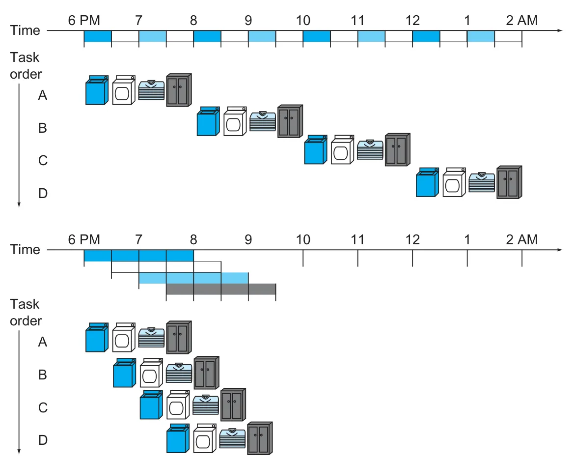
Analogy: Doing Laundry
Section titled “Analogy: Doing Laundry”- Tasks (stages) for completing a load of laundry: wash → dry → fold → store
- Instead of waiting for one load to finish before starting another, each stage is continuously active on a different load
- Pipeline performs like a laundry assembly line: once the line is full, each step outputs a finished product every cycle
Five-Stage Instruction Cycle in MIPS
Section titled “Five-Stage Instruction Cycle in MIPS”Each MIPS instruction may go through the following five stages:
- Instruction Fetch (IF) - Access instruction memory
- Instruction Decode (ID) - Decode and read register operands
- Execute (EX) - Perform ALU operations
- Memory Access (MEM) - Read/write data memory (only for load/store)
- Write Back (WB) - Write result to register file
Not every instruction uses every stage actively, but all must pass through each stage in a pipelined design.
Some instructions like R-format skip MEM, and store instructions skip WB. Branch instructions may skip both MEM and WB. However, all must move through all stages to maintain pipeline structure and timing.
Why Stages Can Overlap
Section titled “Why Stages Can Overlap”Each stage uses a different hardware component in the MIPS datapath: IF uses the instruction memory (IM), ID reads from the register file (Reg), EX runs the ALU, MEM accesses data memory (DM), and WB writes back to the register file. Since no two stages share the same physical component, multiple instructions can be in-flight at once without interfering with each other.

Note that the register file appears at both ends: ID reads the source registers, and WB writes the result back. These use different ports of the register file, and since WB writes in the first half of a clock cycle while ID reads in the second half, they can safely share the same cycle without conflict.
Advantages of Pipelining
Section titled “Advantages of Pipelining”The diagram below shows how pipelining reduces total clock cycles:
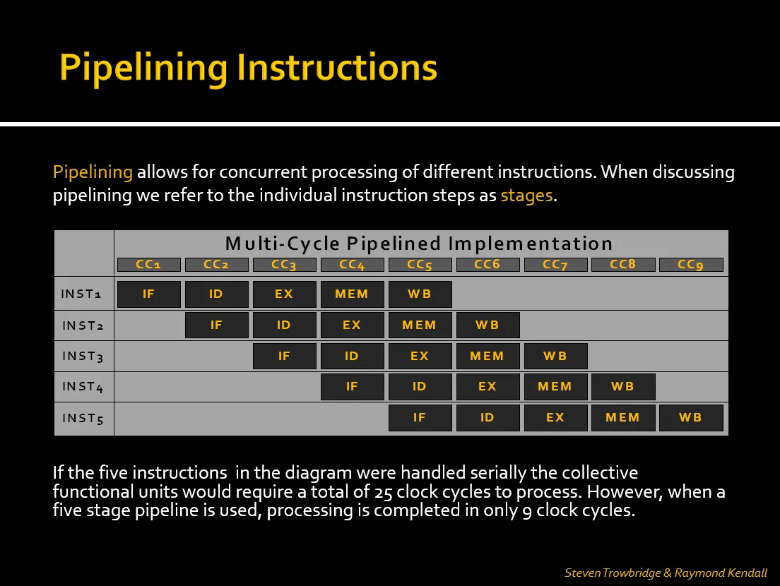
- In a non-pipelined (serial) approach, each instruction must complete before the next begins. With five instructions and five stages per instruction, this would take 25 cycles.
- In a pipelined CPU, overlapping stages allows all five instructions to complete in just 9 clock cycles.
- Throughput Improvement: Completes more instructions per unit time (not faster individual instructions)
- Efficiency: Better hardware utilization compared to single-cycle CPUs
Pipeline Timing & Speedup
Section titled “Pipeline Timing & Speedup”- Pipeline clock cycle is set to the slowest stage (typically MEM or EX)
- With each instruction taking 5 stages, a pipeline allows completion of one instruction per cycle after the pipeline is full
Pipeline Time:
where:
The formula follows from the fact that the first instruction takes k cycles to work through all stages, and each additional instruction adds one more cycle.
So for 5 instructions through a 5-stage pipeline:
In the pipeline visualization above:
- The first few cycles are the fill-up phase, where stages are gradually occupied.
- Once full, one instruction completes every cycle.
- Once all instructions have entered, the pipeline drains one stage at a time.
- Ideal Speedup ≈ number of stages (5), but actual speedup is less due to hazards and pipeline filling/draining overhead
| Model | Instructions | Clock Cycles | Clock Time | Total Time |
|---|---|---|---|---|
| Single-cycle CPU | 5 | 5 cycles | 800 ps | 5 × 800ps = 4000 ps |
| Pipelined CPU | 5 | 9 cycles | 200 ps | 9 × 200ps = 1800 ps |
- The pipeline needs a few cycles to fill at the start and drain at the end, so the performance gain is smaller for short programs.
- With large programs (e.g., 10,000+ instructions), the pipeline stays fully utilized and that fill/drain overhead becomes negligible.
- The performance gain comes from throughput — more instructions finished per unit time — not from making any single instruction faster.
MIPS Design and Pipelining
Section titled “MIPS Design and Pipelining”The MIPS instruction set was purposely designed for pipelined execution in mind. Several of its design decisions directly make pipelining easier to implement:
- Fixed-length instructions — all instructions are 4 bytes, so fetching and decoding are simple and uniform
- Small set of instruction formats — common fields like opcode, rs, and rt always sit in the same bit positions; this means the CPU can start reading source registers from the register file before the opcode is even decoded
- Load/store architecture — memory operands only appear in
lwandsw, simplifying how the pipeline handles memory access - Memory alignment — data must be stored at proper word boundaries (addresses divisible by 4), so a single cycle is always enough for MEM
Together, these keep each pipeline stage simple and predictable, with no complicated special-casing in the control logic.
Pipeline Hazards
Section titled “Pipeline Hazards”A pipeline hazard is anything that stops the next instruction from starting in the next clock cycle.
1. Structural Hazards
Section titled “1. Structural Hazards”Prof kinda glossed over this — said don’t worry too much about it.
- Cause: Two instructions attempt to use the same hardware component simultaneously
- Solution: MIPS avoids these by design (e.g., separate instruction/data memory)
2. Data Hazards
Section titled “2. Data Hazards”- Cause: Dependency between instructions (e.g., one instruction needs a result from another still in progress)
- Types:
-
RAW (Read-After-Write): Most common
e.g.
The
subinstruction needs the value of$t1produced by theaddinstruction:add $t1, $s1, $s2sub $s0, $t1, $t2
-
The diagram below shows how the two instructions are scheduled to run, one right after the other — the instructions overlap in the pipeline as is our intent for maximizing performance, but with a subtle issue: a data hazard. add starts at cycle 1 and sub starts one cycle later — so at cycle 3, while add is in its EX stage, sub is in its ID stage. This is the root of the hazard: sub needs $t1 at its EX stage (CC4) to feed into the ALU, but add won’t write it back to the register file until WB (CC5) — the hazard here is not that this would crash, but that we risk sub using the old (stale) value of $t1 instead of the new one that we intend as the result from add. In order to avoid this hazard, we need to update the behavior of our hardware to ensure that sub gets the correct value computed by add.

Solutions:
Section titled “Solutions:”-
Stalling (Bubbles)
- Pipeline inserts bubbles to delay the dependent instruction.
- Bubbles represent NOPs (no-ops / no operations) — empty operations that pass through the pipeline without reading, writing, or computing anything. They serve to push subsequent instructions forward by one cycle.
- Implemented using a hazard detection unit, which detects the dependency and automatically inserts bubbles.
With two nops inserted,
add’s WB andsub’s ID both land at CC5. Since WB writes in the first half of that cycle and ID reads in the second half, they can safely share it —subreads the correct value from the register file and the hazard is resolved. This half-cycle sharing is also why 2 nops suffice here rather than 3: without it,sub’s ID would have to land strictly afteradd’s WB.
-
Forwarding (Bypassing)
- The computed result physically exists on the data wire right after EX completes — it just hasn’t been written to the register file yet.
- With a forwarding implementation, the dependent instruction’s decoder will still read the old (stale) register value. However, the forwarding unit detects the dependency and overrides that value with the one already sitting on the EX/MEM data line.
- The dependent instruction doesn’t stall — it proceeds normally, getting the correct value substituted in at the ALU input.
- Done using a forwarding unit and multiplexers that select between the register file output and the forwarded value.
- This solution is ideal in our goal of maximizing performance (where we want all our instructions to complete as early as possible), since it eliminates the need for stalls and allows instructions to proceed without delay. However, it does require additional hardware complexity to implement the forwarding paths and control logic.
We consider that
add’s result is computed at the end of its EX stage. Without forwarding,subcan’t use it untiladdwrites it back to the register file at WB, which is two cycles later. With a forwarding unit, there’s a direct hardware path that routes the EX result (now held in the EX/MEM pipeline register) straight to the ALU input ofsub’s own EX stage, bypassing the register file. This is an EX-to-EX forward:add’s result is available at the end of CC3 andsubneeds it at the start of CC4, so the dependency line is vertical at the CC3/CC4 boundary — no stall needed.
Load-Use Hazard
Section titled “Load-Use Hazard”This is a special case of a data hazard. Unlike an R-type instruction (where the result exists on the data wire right after EX), a lw’s EX stage only computes the memory address — the actual loaded value doesn’t exist until the end of MEM. This rules out forwarding from EX, since there’s nothing there yet to forward. If sub follows lw immediately, sub’s EX stage starts at the same cycle as lw’s MEM — one cycle too early to receive the value. Inserting exactly one stall shifts sub’s EX forward by one cycle so it aligns with lw’s MEM output, at which point forwarding delivers the value just in time.
e.g.
lw $s0, 0($t0)sub $t1, $s0, $t2 # Requires 1 stall cycle + forwardingSolutions:
- Stall (nop/bubble): Insert a nop between
lwandsubto create a gap for the loaded value to become available. - Code Scheduling (instruction reordering): The compiler reorders instructions so that an unrelated instruction fills the gap instead of a bubble — eliminating the stall with no extra hardware. Essentially: do loads early, do other work, then use the loaded values.
The diagram below shows the load-use hazard. The dot on lw marks the end of its MEM stage — the earliest point when the loaded value is available. The dot on sub marks the end of its ID stage — the point where it needs the value to proceed into EX. The line connecting the two dots shows the dependency. Notice that sub’s dot (end of cycle 3) falls to the left of lw’s dot (end of cycle 4): sub needs the value one cycle before lw can produce it, which is exactly why a stall must be inserted.

With a nop inserted between lw and sub, both the end of lw’s MEM and the end of sub’s ID land at the same cycle boundary (CC4). The dependency line is now vertical — the loaded value arrives exactly when sub needs it, so forwarding can deliver it with no further stalling.

3. Control Hazards (Branch Hazards)
Section titled “3. Control Hazards (Branch Hazards)”- Cause: Branches alter instruction flow, but the next instruction is fetched before branch resolution
Solutions:
Section titled “Solutions:”- Flush: Discard the incorrectly-fetched instruction when the branch resolves the other way
- Branch prediction: Guess the likely path to avoid stalling; dynamic algorithms can improve accuracy. However, MIPS takes the simpler approach below.
- MIPS Approach - Delayed Branching:
- Always fetch the next instruction after the branch
- The next instruction (delay slot) is always executed, regardless of branch result
- Compiler reorders code to place useful instructions in the delay slot
- Static prediction: MIPS assumes branches are not taken
Hardware Support for Pipelining
Section titled “Hardware Support for Pipelining”Pipeline Inter-Stage Registers
Section titled “Pipeline Inter-Stage Registers”Pipeline registers sit between stages and hold the outputs of each stage until the next stage is ready to consume them. This is what makes overlapping execution possible — each stage can move forward without waiting on the others, because the values are buffered in between.
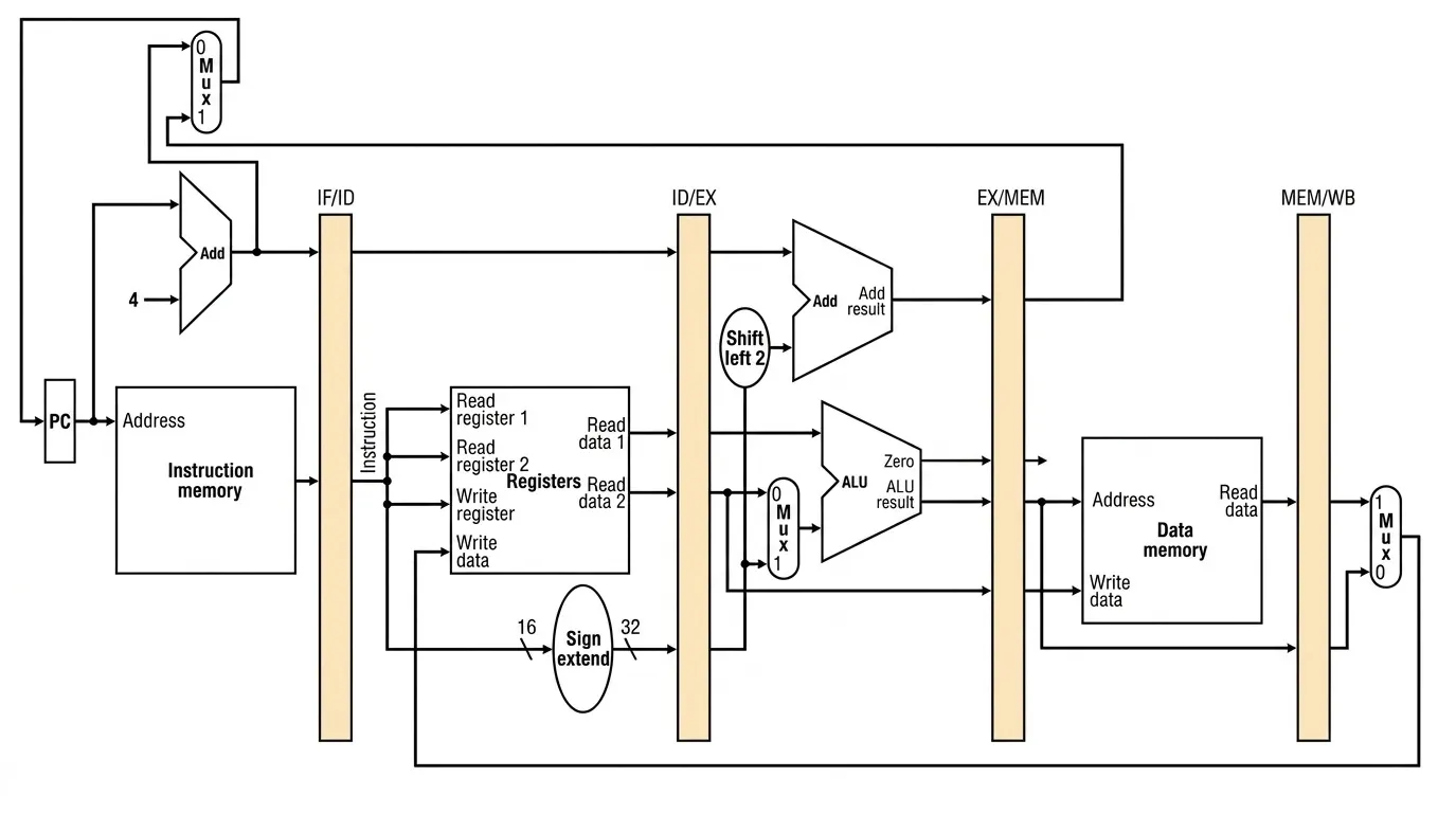
- IF/ID (64 bits): holds the 32-bit fetched instruction and the 32-bit PC+4 value
- ID/EX (128 bits): holds PC+4, two 32-bit register read values, the 32-bit sign-extended immediate, and destination register number
- EX/MEM (97 bits): holds the ALU result, zero flag, write data for stores, and destination register number
- MEM/WB (64 bits): holds the 32-bit data read from memory (or ALU result) and the 5-bit destination register number, to be written back
Forwarding Unit
Section titled “Forwarding Unit”- Contains multiplexers that bypass pipeline registers to feed results directly to dependent stages
- Used to resolve most RAW data hazards without stalling
Hazard Detection Unit
Section titled “Hazard Detection Unit”- Detects RAW hazards that forwarding alone can’t resolve (e.g., load-use) and inserts NOPs (bubbles) to stall the pipeline
- Works in tandem with the forwarding unit: forwarding eliminates most stalls; the hazard detection unit handles the cases where it can’t
Control Unit
Section titled “Control Unit”- Modified in a pipelined CPU to coordinate stalls, instruction flushing on mispredicted branches, and pipeline register updates
Example: Pipelined Execution
Section titled “Example: Pipelined Execution”Consider the following five instructions:
lw $t0, 0($s0) # I1add $t1, $s1, $s2 # I2sub $t2, $t0, $s3 # I3or $t3, $s5, $s6 # I4add $t4, $s7, $t5 # I5 depends on ($t0), but there is one independent instruction () in between. That gap is enough: by the time reaches its EX stage, has finished MEM and the loaded value can be forwarded directly — no stall needed. All five instructions enter the pipeline back-to-back.

Performance Comparison: Pipelined vs. Single-Cycle
Section titled “Performance Comparison: Pipelined vs. Single-Cycle”Assume the following component delays:
| Component | Delay |
|---|---|
| Memory unit (IM, DM) | 200 ps |
| ALU, adders | 100 ps |
| Register file (read or write) | 50 ps |
Pipelined Execution Time
Section titled “Pipelined Execution Time”The pipeline clock is set to the slowest individual stage, which is the memory unit at . With instructions and stages:
Single-Cycle Execution Time
Section titled “Single-Cycle Execution Time”In a single-cycle CPU, the clock is fixed to the longest instruction. We already know from the previous lecture that lw is the longest, since it’s the only instruction that actively uses all five stages. We just need to determine exactly how long it takes by adding up its stage delays:
lw
That gives 600 ps, so the clock is set to 600 ps and every instruction takes one full cycle regardless of type:
Speedup
Section titled “Speedup”So the pipelined approach is about 1.67 times faster than the single-cycle baseline for this sequence of instructions, due to the overlapping execution and the ability to use a shorter clock cycle.
Suggested Reading
Section titled “Suggested Reading”- Hennessy & Patterson textbook chapters on pipelining, data hazards, and control hazards
- Study older student presentations (e.g., by Steven Trowbridge & Raymond Kendall)
- Practice interpreting pipeline diagrams like the ones above