Lec 04-22-2025 & 04-29-2025: Intro to Cache; Direct-Mapped Cache Design & Size Calculations | CSCI 343
Cache is a small amount of memory that is faster than main memory. It sits between normal main memory and the CPU, and may be located on the CPU chip itself or on a separate module.
Cache Operations: Overview
Section titled “Cache Operations: Overview”-
- CPU requests the contents of a memory location
- The cache is checked for this data
- If present, the data is retrieved from cache (fast)
- If not present, the required block is read from main memory into cache
- The data is then delivered from cache to the CPU
Cache includes tags to identify which block of main memory is currently stored in each cache slot.
Why Cache Exists: The Principle of Locality
Section titled “Why Cache Exists: The Principle of Locality”Main memory is slow compared to the CPU. Cache is a small, fast memory that sits between them and holds copies of recently accessed or likely-to-be-needed data. The idea behind cache is that programs tend to access the same memory locations repeatedly, or locations that are close together. This observation breaks down into two principles:
Temporal Locality: When an instruction is executed or data is accessed, it is stored in the cache because there is a high probability it will be accessed again.
eg. (loop variables)
while (condition) { i++; // access variable} // for 100 iterations, the variable would be referenced again and againSpatial Locality: When an instruction is executed or data is accessed, nearby items are also loaded into the cache because there’s a high probability they’ll be accessed soon.
eg. Arrays and vectors — if you access arr[0], you’re likely going to access arr[1], arr[2], etc. soon after. Cache takes advantage of this by loading a whole block of consecutive memory (not just the one requested word) on a cache miss.
How Does Hardware Decide What to Cache?
Section titled “How Does Hardware Decide What to Cache?”Taking advantage of temporal locality:
- Bring data into cache whenever it’s referenced
- Kick out something that hasn’t been used recently
Taking advantage of spatial locality:
- Bring in a block of contiguous data (a cacheline), not just the requested data
Cache Hits, Misses, and Hit Ratio
Section titled “Cache Hits, Misses, and Hit Ratio”Cache Hit: a memory access where the data is already in cache
Cache Miss: a memory access where data isn’t in the cache
Cache block size (or cache line size): the amount of data that gets transferred on a cache miss
Hit ratio: (# of cache hits) / (# of total accesses)
Hit time: the time needed to access the cache
Miss penalty: the time to replace a block from the upper level (cache) with a block from the lower level (main memory)
The hit ratio is a measure of how effectively the cache is being used. A higher hit ratio means fewer accesses of the slower main memory component.
Caches can also be divided by what kind of content they hold:
- Instruction cache (I-cache): a cache that can only hold instructions
- Data cache (D-cache): a cache that can only hold data
- Unified cache: a cache that holds both data and instructions
Consider this sequence of memory block accesses (consider each number as a block number):
indicates a miss.
indicates a hit.
The first access to block 5 is always a miss (it’s not in cache yet). But the next three accesses to block 5 are hits — this is temporal locality at work. Block 6 is a miss when first accessed, then a hit afterwards. Block 7 is a miss (first time seen). The final access to block 5 is a hit because it was accessed recently enough to still be in cache.
Cache Design
Section titled “Cache Design”Designing a cache means making decisions along several dimensions:
- Size
- Mapping function
- Replacement algorithm
- Write policy
- Block size
- Number of caches
Data Gets Into Cache via Reads Only
Section titled “Data Gets Into Cache via Reads Only”Data enters the cache through read operations only. When you write to memory, you are writing a result you have already computed in the CPU, so there’s no reason to fetch it from memory first. Cache stores data that was read from memory, not data being sent back to it.
This raises a question: when cached data is modified, how does main memory get updated? That’s handled by the write policies:
Write Policies:
- Write-through: Update RAM every time cache is updated. Simpler, but generates more memory traffic.
- Write-back: Delay RAM update until the block is evicted from cache. More efficient, but requires tracking which lines have been modified (using a “dirty bit”).
Cache/Memory Example: (read A, read B, write C)
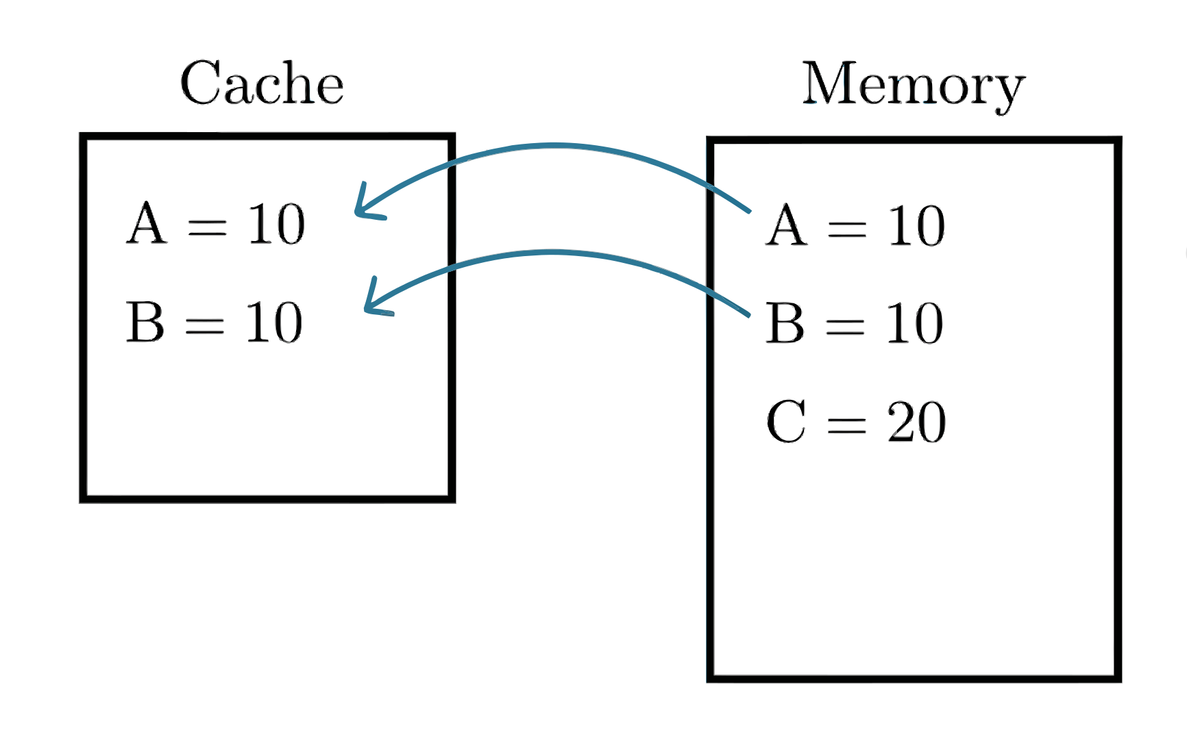
A and B are read into cache so the CPU can operate on them. C is the write result — it goes back to memory (and may or may not update cache depending on the write policy).
What we bring into the cache is based on the principle of locality.
Replacement Policies:
- When cache is full, a line must be replaced
- Most common strategy: Least Recently Used (LRU)
Direct Mapping
Section titled “Direct Mapping”For direct Mapping, each block of main memory maps to only one cache line, determined by:
This means multiple memory blocks compete for the same cache line. For example, with a 4-line cache (lines 0—3) and 32 memory blocks (0—31):
- Line 0 holds: block 0, 4, 8, 12, 16, 20, …
- Line 1 holds: block 1, 5, 9, 13, 17, 21, …
If block 4 is currently in line 0 and you access block 16, block 4 gets evicted — even if block 4 was still needed. This is a known limitation of direct mapping.
Cache: Direct Mapping Address Structure
Section titled “Cache: Direct Mapping Address Structure”Tag and Line Number: Address Breakdown
Section titled “Tag and Line Number: Address Breakdown”When a block is loaded into cache, we need to remember which memory block it came from — otherwise we can’t tell on a later access whether we have the right data or stale data from a different block that shares the same cache line.
The straightforward solution would be to store the full block number alongside the data, but that wastes space. Instead, we store only the bits we actually need:
With a 4-line cache, any block number that is a multiple of 4 maps to line 0, any block number that is a (multiple of 4) + 1 maps to line 1, and so on:
Line 0:
| Mem block # | block # binary |
|---|---|
| block 0 | |
| block 4 | |
| block 8 | |
| block 12 | |
Line 1:
| Mem block # | block # binary |
|---|---|
| block 1 | |
| block 5 | |
| block 9 | |
| block 13 | |
Notice that all blocks in line 0 end in 00, and all blocks in line 1 end in 01. That’s not a coincidence — the last 2 bits are the cache line index (since is just the bottom 2 bits of the number). Because we already know which line we’re looking at, those bottom bits are redundant. We don’t need to store them.
What we do need to store is the remaining top bits — enough to distinguish which of the many blocks mapped to this line is currently stored here. This truncated block number is called the tag.
- Tag = top bits of the block number (unique identifier for which block occupies a line)
- Line number = lower bits (used to index into the cache; derived from the address, not stored)
General Formula
Section titled “General Formula”- Address size: bits (memory size )
- Cache size: lines (line index size bits)
- Tag size
Example:
- Memory has 32 blocks 5-bit address ()
- Cache has 4 lines 2-bit line # ()
- Tag bits
Cache Structure
Section titled “Cache Structure”Each cache line contains:
- Valid/Invalid bit (V/I): Indicates if the data is valid
- Tag: Used for identifying the block stored
- Data: The contents of the block
Cache Line Format
Section titled “Cache Line Format”Tag and data bit width will depend on the system being described.
Adding Word and Byte Fields to the Address
Section titled “Adding Word and Byte Fields to the Address”So far we’ve been working with the simplest case: one word per block, word-addressed. In that case, the address breaks down cleanly into just a tag and a line index.
But in real systems, a cache block usually holds multiple words (to take advantage of spatial locality — you bring in a neighborhood of data, not just the one word you asked for). And processors often use byte addressing, meaning an address points to an individual byte rather than a whole word.
These situations can add up to two more fields to the address:
- Word index ( bits): selects which word within a multi-word block you want. If there’s only 1 word per block, this field doesn’t exist.
- Byte offset ( bits): selects which byte within a word. Only present if the system uses byte addressing.
This address is just the ordinary memory address the CPU generates for a memory reference (eg. from a load/store instruction, instruction fetch, etc). A system’s memory address partitioning scheme is influenced by the structure of the CPU’s cache.
For a direct-mapped cache, the full address partitioning is:
- = Total address bits
- = Bits for line index
- = Bits for word index (if multiple words per block; if only 1 word per block, we don’t include a partition for the word index)
- = Bits for byte index (if the system uses byte addressing; otherwise we don’t include this partition for the byte index)
Address Decomposition Scenarios
Section titled “Address Decomposition Scenarios”- Word Addressing, 1 word per block
- Word Addressing, multiple words per block
- Byte Addressing, 1 word per block, word size bytes
- Byte Addressing, multiple words per block
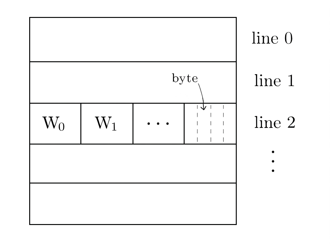
Example of a cache with multiple words per block and byte addressing:
Cache Initialization and Context Switching
Section titled “Cache Initialization and Context Switching”- On program startup: all cache lines are marked invalid
- On context switch:
- Previous process’s cache data becomes irrelevant
- All cache lines are again marked invalid
- Valid bit is set to 1 only when new block data is loaded
Total Cache Size Calculation
Section titled “Total Cache Size Calculation”Example:
We wish to find the total # of bytes for a direct mapping cache to store 64 KB in 1-word blocks, assuming a word size of 32 bits and MIPS addressing.
Solution:
Break down the specifications:
- Word size bits
- Block size word
- Addressing mode: byte addressing (from what we know of MIPS)
- Data: 64 KB
Block size is only 1 word, so we don’t need to allocate any bits for word select.
MIPS uses byte addressing, so we need to allocate bits for addressing the byte # in a word.
The word size is 32 bits which implies a 32-bit address size.
So the address structure should be:
Now we compute the bit width of each partition:
With direct mapping, there is exactly one cache line per block of data — each line holds exactly one block. So the number of lines equals the number of blocks that fit in the cache’s data capacity:
Since 2 bits for byte # and 14 bits for line # are already taking up part of the 32 bits of the address size:
Address Structure:
Since we know generally that the cache line format looks like this:
Then the overall cache structure should follow, given that we now know the bit width for Tag and Data (which is the block size).
Cache Structure:
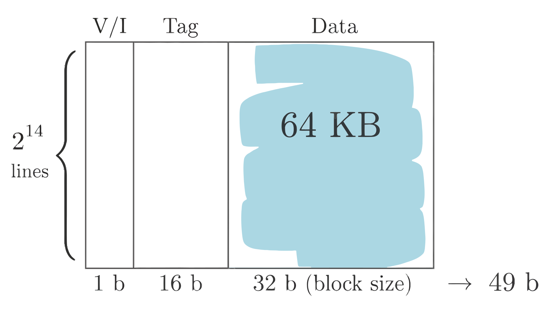
Each line is bits.
Total cache size: