Skip to content

Lec 02-27-2025: Unused States & Synchronous Counters | CSCI 343

With nn flip-flops, a circuit can represent up to 2n2^n distinct states. Sometimes a sequential circuit needs fewer than that — for example, a circuit cycling through 5 specific states will require 3 flip-flops (since 22=42^2=4 is too small but 23=82^3=8 is enough), leaving 3 unused states.

Those unused states are not included in the state table and are treated as don’t-care conditions in the K-maps, giving the minimization more flexibility. It is also useful to provide a master-reset input whose purpose is to initialize the states of all flip-flops to a known valid state on startup.

Q(t)InputQ(t+1)f/fInputsOutputABCxABCSARASBRBSCRCy00100010X0XX0000110100X1001001000110XX0100010110010010X001100010X01X00011110010010101000101X00X1001001100X00X0X11010001010XX001011100X00X011\begin{array}{ccc|c|ccc|cccccc|c} & Q(t) & & \text{Input} & & Q(t{+}1) & & & & \text{f/f} & \text{Inputs} & & & \text{Output} \\ \hline A & B & C & x & A & B & C & S_A & R_A & S_B & R_B & S_C & R_C & y \\ \hline 0 & 0 & 1 & 0 & 0 & 0 & 1 & 0 & X & 0 & X & X & 0 & 0 \\ 0 & 0 & 1 & 1 & 0 & 1 & 0 & 0 & X & 1 & 0 & 0 & 1 & 0 \\ 0 & 1 & 0 & 0 & 0 & 1 & 1 & 0 & X & X & 0 & 1 & 0 & 0 \\ 0 & 1 & 0 & 1 & 1 & 0 & 0 & 1 & 0 & 0 & 1 & 0 & X & 0 \\ 0 & 1 & 1 & 0 & 0 & 0 & 1 & 0 & X & 0 & 1 & X & 0 & 0 \\ 0 & 1 & 1 & 1 & 1 & 0 & 0 & 1 & 0 & 0 & 1 & 0 & 1 & 0 \\ 1 & 0 & 0 & 0 & 1 & 0 & 1 & X & 0 & 0 & X & 1 & 0 & 0 \\ 1 & 0 & 0 & 1 & 1 & 0 & 0 & X & 0 & 0 & X & 0 & X & 1 \\ 1 & 0 & 1 & 0 & 0 & 0 & 1 & 0 & 1 & 0 & X & X & 0 & 0 \\ 1 & 0 & 1 & 1 & 1 & 0 & 0 & X & 0 & 0 & X & 0 & 1 & 1 \\ \end{array}

We notice from the table we’re missing states ABC = 000, 110, and 111 so these are the unused states — they are missing for both the x=0x=0 and x=1x=1 transitions. Unused states become don’t-care conditions in the K-maps.

A self-correcting circuit is one that, if it enters an unused or invalid state (due to noise, glitches, or other errors), can transition back to a valid state without external intervention. This is a desirable property because it means the circuit can recover from transient faults on its own, improving reliability. To check if a circuit is self-correcting, we can analyze the state transitions from the unused states and see if they lead back to valid states. For that, we’ll need to determine the flip-flop input expressions from the K-maps:
SA:S_A:

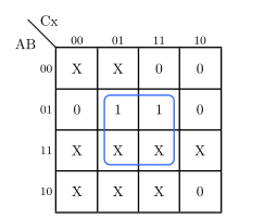
K-map for S_A: rows AB, cols Cx; cells: X X 0 0 / 0 1 0 1 / X X X X / X X 0 X; group on cols 01+11 rows 01+11 gives S_A = Bx

SA=BxS_A = Bx

RA:R_A:

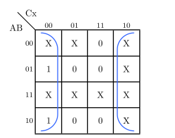
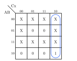
K-map for R_A: rows AB, cols Cx; one 1 at AB=10 col Cx=10; circle gives R_A = Cx'

RA=CxR_A = Cx'

SB:S_B:

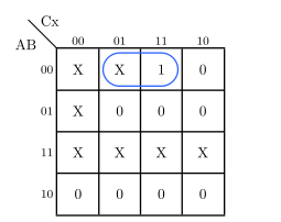
K-map for S_B: rows AB, cols Cx; one 1 at AB=00 col Cx=11, expanded with don't-care at col Cx=01; circle gives S_B = A'B'x

SB=ABxS_B = A'B'x

RB:R_B:

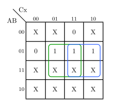
K-map for R_B: rows AB, cols Cx; 1s at AB=01 cols 01 and 10, and AB=01 col 11; group cols 01+11 rows 01+11 (green) and cols 11+10 rows 01+11 (blue) gives R_B = Bx + BC

RB=Bx+BCR_B = Bx + BC

SC:S_C:

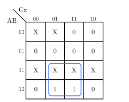
K-map for S_C: rows AB, cols Cx; 1s at AB=01 and AB=10 in col Cx=00 and Cx=10 (wrap-around); circle gives S_C = x'

SC=xS_C = x'

RC:R_C:

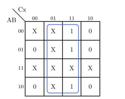
K-map for R_C: rows AB, cols Cx; 1s in col Cx=11 rows AB=00,01,10; group cols 01+11 all rows gives R_C = x

RC=xR_C = x

y:y:

K-map for y: rows AB, cols Cx; 1s at AB=10 cols 01 and 11; group cols 01+11 rows 10+11 gives y = Ax

y=Axy = Ax

We plug each unused state into the derived flip-flop input expressions to determine the next state. To do this, we evaluate its SS and RR inputs for the given state and consider the semantics of the flip flop’s inputs (as described by its characteristics table). For example, S=1,R=0S=1, R=0 sets the output to 1; S=0,R=1S=0, R=1 resets it to 0; etc.

Unused state ABC = 000:

SA=Bx=0RA=Cx=0no change to ASB=ABx=xRB=Bx+BC=0B dependent on xSC=xRC=xC dependent on x\begin{aligned} S_A &= Bx = 0 \quad \quad & R_A &= Cx' = 0 & &\Rightarrow \text{no change to } A \\ S_B &= A'B'x = x & R_B &= Bx + BC = 0 & &\Rightarrow B \text{ dependent on } x \\ S_C &= x' & R_C &= x & &\Rightarrow C \text{ dependent on } x \end{aligned}

The inputs of flip flops BB and CC depend on xx, so we check the two cases:

  • x=0x = 0:
SB=ABx=110=0RB=0no change to BSC=x=1RC=x=0set C to 1\begin{aligned} S_B &= A'B'x = 1 \cdot 1 \cdot 0 = 0 \quad & R_B &= 0 & \quad &\Rightarrow \text{no change to } B \\ S_C &= x' = 1 & R_C &= x = 0 & &\Rightarrow \text{set } C \text{ to } 1 \end{aligned} 0000001000 \xrightarrow{0} 001
  • x=1x = 1:
SB=ABx=111=1RB=0set B to 1SC=x=0RC=x=1reset C to 0\begin{aligned} S_B &= A'B'x = 1 \cdot 1 \cdot 1 = 1 \quad & R_B &= 0 & \quad &\Rightarrow \text{set } B \text{ to } 1 \\ S_C &= x' = 0 & R_C &= x = 1 & &\Rightarrow \text{reset } C \text{ to } 0 \end{aligned} 0001010000 \xrightarrow{1} 010

Both states 001 and 010 are valid, so the circuit self-corrects out of state 000. The same analysis can be applied to other invalid states 110 and 111.

Having covered how to handle unused states in a general sequential circuit design, we now turn to a specific and common application of this design process: synchronous counters.

A synchronous counter is a sequential circuit that goes through a predefined sequence of states upon application of input pulses. Counters are useful for generating timing sequences to control operations in a digital system and have no external input. Counters must cycle through a fixed sequence of states, without holding. Once it arrives at a state, it must move on to the next state in the sequence on the next clock pulse.

Two types of counters we’ll look at are:

  • Binary counters that cycle through states in binary counting order (e.g., 00, 01, 10, 11).
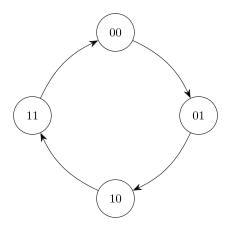
DFA of a 2-bit binary counter cycling 00→01→10→11→00

  • Non-binary counters that cycle through a subset of states, skipping others (e.g., 000, 001, 010, 100 — skipping 011, 101, 110, 111).
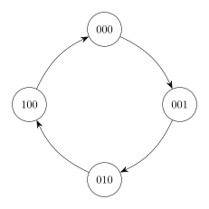
DFA of a non-binary counter cycling 000→001→010→100→000, skipping 011, 101, 110, 111

A 3-bit counter might cycle through states 0 through 7 (then back to 0):

0123456700 \to 1 \to 2 \to 3 \to 4 \to 5 \to 6 \to 7 \to 0 \to \cdots

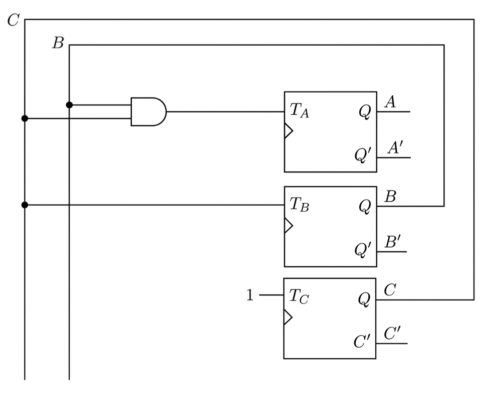
T flip-flops are generally considered the better choice for building synchronous counters due to their toggling behavior. As we count upward, each bit in a counter either toggles or holds; it never needs to be set or reset independently, which is exactly what the T flip-flop’s two inputs express:

  • T=0T = 0: no change
  • T=1T = 1: Q(t)Q'(t)   (output toggles)
Q(t)Q(t+1)f/fInputsABCABCTATBTC000001001010010011011100100101101110110111111000\begin{array}{ccc|ccc|ccc} & Q(t) & & & Q(t{+}1) & & \text{f/f} & \text{Inputs} & \\ \hline A & B & C & A & B & C & T_A & T_B & T_C \\ \hline 0 & 0 & 0 & 0 & 0 & 1 & & & \\ 0 & 0 & 1 & 0 & 1 & 0 & & & \\ 0 & 1 & 0 & 0 & 1 & 1 & & & \\ 0 & 1 & 1 & 1 & 0 & 0 & & & \\ 1 & 0 & 0 & 1 & 0 & 1 & & & \\ 1 & 0 & 1 & 1 & 1 & 0 & & & \\ 1 & 1 & 0 & 1 & 1 & 1 & & & \\ 1 & 1 & 1 & 0 & 0 & 0 & & & \\ \end{array}

Using the T flip-flop excitation table, we can determine the required T inputs for each flip-flop to achieve the desired state transitions:

Q(t)Q(t+1)T000011101110\begin{array}{cc|c} Q(t) & Q(t+1) & T \\ \hline 0 & 0 & 0 \\ 0 & 1 & 1 \\ 1 & 0 & 1 \\ 1 & 1 & 0 \\ \end{array}

Applying this to each flip-flop:

Q(t)Q(t+1)f/fInputsABCABCTATBTC000001001001010011010011001011100111100101001101110011110111001111000111\begin{array}{ccc|ccc|ccc} & Q(t) & & & Q(t{+}1) & & \text{f/f} & \text{Inputs} & \\ \hline A & B & C & A & B & C & T_A & T_B & T_C \\ \hline 0 & 0 & 0 & 0 & 0 & 1 & 0 & 0 & 1 \\ 0 & 0 & 1 & 0 & 1 & 0 & 0 & 1 & 1 \\ 0 & 1 & 0 & 0 & 1 & 1 & 0 & 0 & 1 \\ 0 & 1 & 1 & 1 & 0 & 0 & 1 & 1 & 1 \\ 1 & 0 & 0 & 1 & 0 & 1 & 0 & 0 & 1 \\ 1 & 0 & 1 & 1 & 1 & 0 & 0 & 1 & 1 \\ 1 & 1 & 0 & 1 & 1 & 1 & 0 & 0 & 1 \\ 1 & 1 & 1 & 0 & 0 & 0 & 1 & 1 & 1 \\ \end{array}

With the table filled in, we can minimize each of the three flip-flop input expressions using K-maps. Each K-map has three variables: A, B, and C.
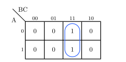
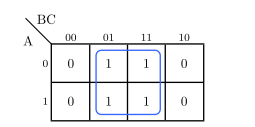
TA:T_A:

K-map for T_A: rows A, cols BC; single group of two 1s at BC=11 for both rows A=0 and A=1; gives T_A = BC

TA=BCT_A = BC

TB:T_B:

K-map for T_B: rows A, cols BC; group of four 1s spanning cols BC=01 and BC=11 for both rows A=0 and A=1; gives T_B = C

TB=CT_B = C

TC:T_C:

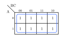
K-map for T_C: rows A, cols BC; all eight cells are 1; gives T_C = 1

TC=1T_C = 1